
 Online Shop
 English
 China - 简体中文
 Global - English
 Brazil - Português
 Netherlands - Dutch
 Italy - Italiano
 Germany - Deutsch
 Spain - Español
 France - Français
 Vietnam - Tiếng Việt
 Poland - Polski
 Australia - English
 Japan - 日本語
Blog

Advanced Three-Phase String Inverter for High-Performance Commercial Solar Systems
Introduction
Modern commercial and industrial solar installations require more than basic energy conversion. They need stable grid interaction, flexible photovoltaic design, dependable protection, intelligent monitoring, and efficient operation across changing environmental conditions. The SUN-18/20/22/23/25K-G06P3-EU-AM2 series is designed to meet these requirements as a three-phase string inverter family covering rated output powers from 18 kW to 25 kW.
Developed for grid-connected photovoltaic applications, this inverter series combines two maximum power point tracking channels, high conversion efficiency, broad voltage compatibility, integrated protection functions, and communications options for system monitoring. The product is suitable for commercial rooftops, small industrial facilities, agricultural buildings, educational sites, retail premises, and other distributed generation projects where high availability and predictable energy production are essential.
The product family provides five power classes: 18 kW, 20 kW, 22 kW, 23 kW, and 25 kW. This range allows system designers to select an output rating that closely matches the photovoltaic array and local grid requirements instead of relying on a single oversized or undersized inverter. The common platform also simplifies project engineering, installation planning, spare-parts management, and technical training.
With a maximum efficiency of up to 98.2%, a European efficiency of up to 97.7%, and an MPPT efficiency exceeding 99%, the series is engineered to convert a high proportion of available solar energy into usable three-phase AC power. Its wide MPPT operating range, high maximum PV input voltage, optional monitoring functions, and extensive safety features further support reliable operation in demanding commercial environments.
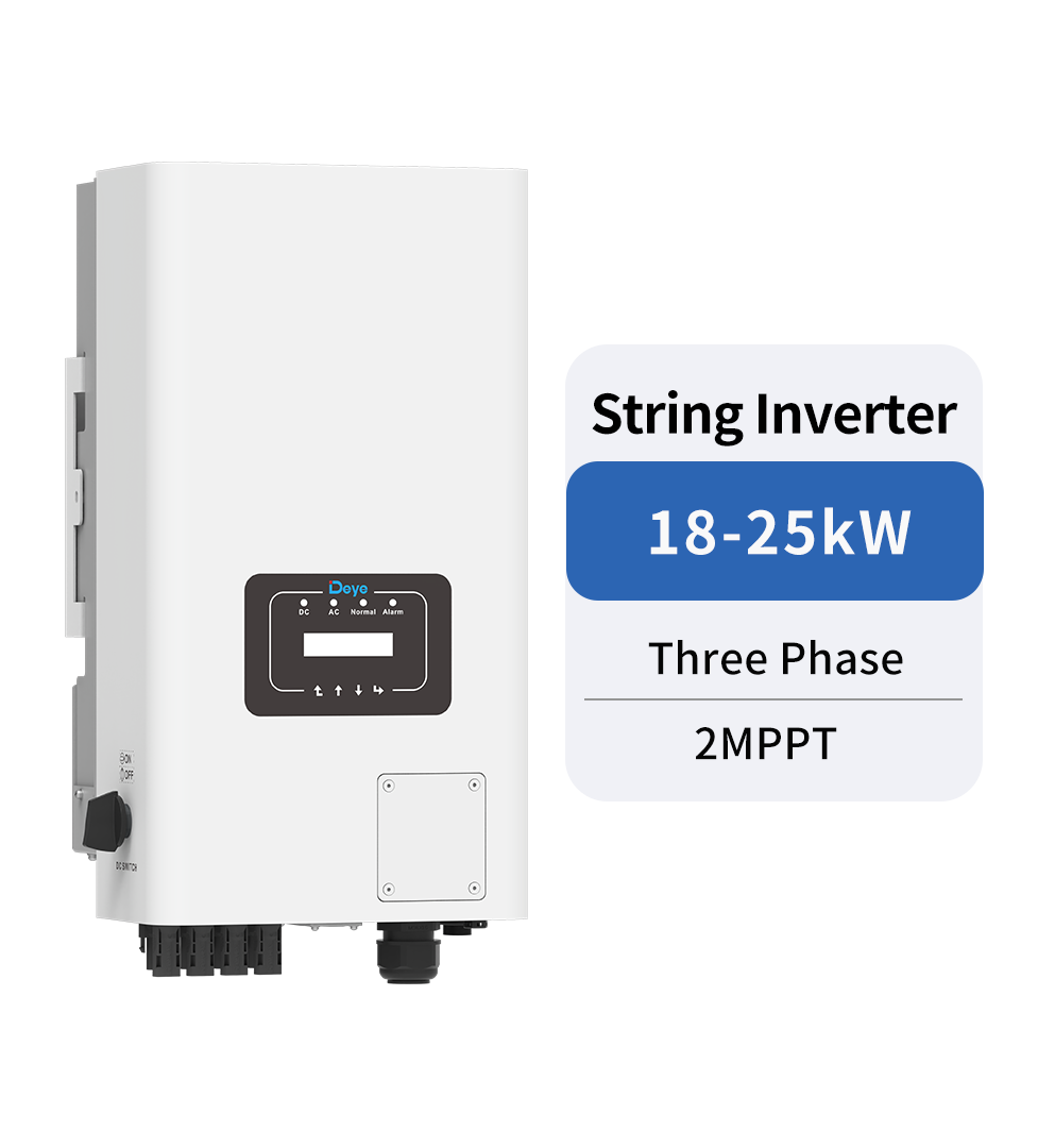
SUN-18/20/22/23/25K-G06P3-EU-AM2
Product Positioning and Application Value
The SUN-18/20/22/23/25K-G06P3-EU-AM2 belongs to the three-phase string inverter category. Unlike central inverter architectures that collect many photovoltaic strings in a separate high-power conversion unit, a string inverter is installed closer to the PV field and manages a smaller group of strings. This architecture can offer greater design flexibility, easier fault isolation, and convenient expansion across multiple roof areas or building sections.
The product is particularly appropriate for systems where roof orientation, shading patterns, module types, or installation areas differ. Two independent MPP trackers allow the designer to connect PV strings with different operating characteristics to separate tracking channels. This can improve energy harvesting when arrays are installed on different roof pitches or orientations.
The five available output ratings also provide a practical solution for projects with different electrical loads and grid connection limits. A facility with a moderate daytime load may use the 18 kW or 20 kW model, while a larger commercial roof or industrial building may benefit from the 22 kW, 23 kW, or 25 kW version. The shared product architecture ensures that the selection process remains straightforward across a multi-site installation program.
The inverter supports zero-export applications and VSG applications. Zero-export control is valuable where the site owner wishes to consume solar energy locally without sending excess electricity to the public grid, or where local regulations restrict export. VSG, or virtual synchronous generator functionality, can support grid-forming or grid-supportive operating strategies in appropriate system configurations. These functions increase the product’s relevance for modern energy management projects rather than limiting it to conventional feed-in photovoltaic systems.
Typical Applications
Commercial rooftops are a key application. Office buildings, warehouses, shopping facilities, and light manufacturing sites often have large roof surfaces and meaningful daytime electricity demand. A three-phase inverter in the 18 kW to 25 kW class can serve as a building block within a larger distributed system, with several units connected in parallel across different array sections.
Agricultural and rural installations can also benefit from the product. Farms, irrigation facilities, cold-storage buildings, and processing workshops commonly have three-phase loads and large roof or ground-mounted PV areas. The IP65 enclosure rating and broad operating temperature range support installation in a variety of outdoor or semi-outdoor locations when the equipment is mounted according to the installation instructions.
Small industrial systems may use several inverters to achieve the required total capacity. This distributed approach can reduce the impact of a single-unit fault. If one inverter requires service, the remaining units may continue operating, depending on the system design and applicable protection requirements.
Educational, public-service, and multi-building sites can also use the series as part of a modular solar program. A common inverter family across several buildings helps standardize commissioning procedures, monitoring arrangements, maintenance routines, and replacement planning.
Core Electrical Design
Two MPP Trackers for Flexible Array Configuration
The inverter includes two MPP trackers with two strings per MPP tracker. Maximum power point tracking continuously adjusts the DC operating point so that the PV array can produce as much power as possible under current irradiance and temperature conditions. The stated MPPT efficiency is greater than 99%, supporting effective energy extraction during changing weather conditions.
Two independent trackers are advantageous when the PV array cannot be arranged as one uniform surface. For example, one tracker may be connected to a group of modules facing southeast while the second serves modules facing southwest. They can also help separate strings affected by different levels of shading, although professional system design remains necessary to minimize shading in the first place.
Compared with a single-tracker design, the dual-MPPT arrangement can reduce mismatch losses caused by different string conditions. It also offers greater freedom when configuring arrays around skylights, ventilation equipment, roof edges, dormers, and other obstacles.
Wide DC Voltage Compatibility
The maximum PV input voltage is 1100 V, while the startup voltage is 150 V. The MPPT voltage range extends from 200 V to 1000 V, and the rated PV input voltage is 600 V. This combination supports a broad range of commercial PV string designs and gives system engineers flexibility when selecting module quantities per string.
A wide operating voltage window is useful because the voltage of a PV string changes with temperature and irradiance. Cold conditions can increase open-circuit voltage, while high module temperatures can reduce operating voltage. The inverter’s wide voltage range helps designers maintain stable operation across seasonal conditions, provided that the string design stays within all applicable limits.
The 1100 V maximum input voltage can also help reduce the number of parallel strings or the amount of DC cabling required in certain system designs. Longer strings may allow more efficient use of cable infrastructure, although actual string length must always be calculated using the selected module’s temperature coefficients, local minimum temperature, maximum system voltage, and applicable electrical regulations.
High PV Oversizing Capability
The maximum recommended PV input power varies according to the model. The 18 kW model accepts up to 27 kW of PV input power, while the 20 kW model accepts up to 30 kW. The 22 kW model supports up to 33 kW, the 23 kW model up to 34.5 kW, and the 25 kW model up to 37.5 kW.
This DC-to-AC sizing flexibility enables designers to install a larger PV array than the inverter’s nominal AC output in suitable conditions. Such oversizing can improve annual energy yield by allowing the array to operate closer to the inverter’s useful power range during mornings, afternoons, winter periods, and overcast conditions. The correct ratio depends on the local climate, roof orientation, module selection, and grid requirements.
Oversizing should not be treated as permission to exceed the specified electrical limits. Maximum PV power, maximum input voltage, short-circuit current, operating current, and MPPT range must all be verified during design. Proper sizing balances additional annual energy production against possible clipping during periods of high irradiance.
Input Current Capacity
The series is designed for modern PV modules and higher-current string configurations. Depending on the model, the maximum input short-circuit current is specified as 32+32 A or 36+32 A, and the maximum operating PV input current is specified as 48+48 A or 54+48 A. These values provide useful compatibility with contemporary high-power modules when the array is correctly configured.
Because PV module electrical characteristics differ significantly between manufacturers and product generations, installers should compare the module’s maximum operating current and short-circuit current with the inverter’s input limits. The use of current-compatible modules helps preserve operating stability and ensures that the system remains within its design envelope.
AC Output Performance
The inverter family delivers three-phase AC power at rated active outputs of 18 kW, 20 kW, 22 kW, 23 kW, or 25 kW. Maximum apparent power is respectively 19.8 kVA, 22 kVA, 24.2 kVA, 25.3 kVA, and 27.5 kVA. This provides capacity for active power production while accommodating reactive power operation within the specified limits.
Rated AC output current ranges from 27.3/26.1 A for the 18 kW model to 37.9/36.3 A for the 25 kW model. Maximum AC output current ranges from 30/28.7 A to 41.7/39.9 A, depending on the model and rated voltage condition. These ratings assist engineers in selecting AC cables, circuit breakers, disconnect devices, and protection equipment.
The output voltage supports 220/380 V and 230/400 V systems, with a voltage operating range of 0.85Un to 1.1Un and a three-line, neutral, and protective-earth arrangement. The frequency options include 50 Hz with a 45–55 Hz range and 60 Hz with a 55–65 Hz range. This allows the product family to serve a wide range of international grid environments when the relevant grid code and inverter configuration are correctly applied.
The power factor adjustment range extends from 0.8 leading to 0.8 lagging. This capability allows the inverter to provide or absorb reactive power according to the requirements of the local network operator or project design. Reactive power control can be important in commercial systems where voltage management, grid support, or a specific interconnection agreement is required.
Total current harmonic distortion is less than 3%, and DC injection current is less than 0.5% of rated current. Low harmonic distortion helps support power quality, while low DC injection reduces the risk of unwanted transformer saturation or other grid-side effects. Actual performance depends on system conditions, grid impedance, installation quality, and compliance with applicable standards.
Efficiency and Energy Yield Advantages
Conversion efficiency directly affects the value of a solar installation. Every percentage point of efficiency influences the amount of solar energy delivered to the AC system and the amount of heat that must be managed inside the inverter. The series achieves a maximum efficiency of up to 98.2% and a European efficiency of up to 97.7%.
Maximum efficiency is normally achieved under favorable loading and environmental conditions, while European efficiency is intended to represent performance across a weighted operating profile. Both figures are useful, but annual energy yield also depends on temperature, irradiance, array orientation, clipping, grid availability, nighttime consumption, and system downtime.
The MPPT efficiency exceeding 99% complements the conversion efficiency. This means the inverter is designed not only to convert DC power efficiently but also to identify and maintain an effective operating point for the PV strings. In practical installations, accurate tracking can be especially valuable during passing clouds, partial shading, and rapidly changing irradiance.
High efficiency can provide several system-level benefits. It may reduce thermal stress, support a smaller heat dissipation requirement, and improve the energy output obtained from a fixed roof area. For commercial customers, the result can be a stronger relationship between installed PV capacity and annual electricity savings.
Thermal Management
The inverter uses intelligent air cooling. Active thermal management helps control internal temperature during high-power operation and supports stable performance over a broad ambient range. The specified operating temperature range is from -25°C to +60°C, with derating above 45°C.
Derating at elevated temperature is a normal engineering measure that protects the equipment and maintains safe operation. During site planning, installers should provide sufficient clearance around the inverter, avoid locations with direct heat accumulation, and follow the manufacturer’s ventilation requirements. Correct placement can help delay the onset of thermal derating and improve long-term reliability.
Intelligent cooling also supports practical maintenance. Air-cooled systems generally use a familiar thermal management approach that can be inspected and serviced using standard procedures. The installation environment should nevertheless be kept reasonably clean, and accumulated dust or obstructions should be addressed as part of scheduled maintenance.
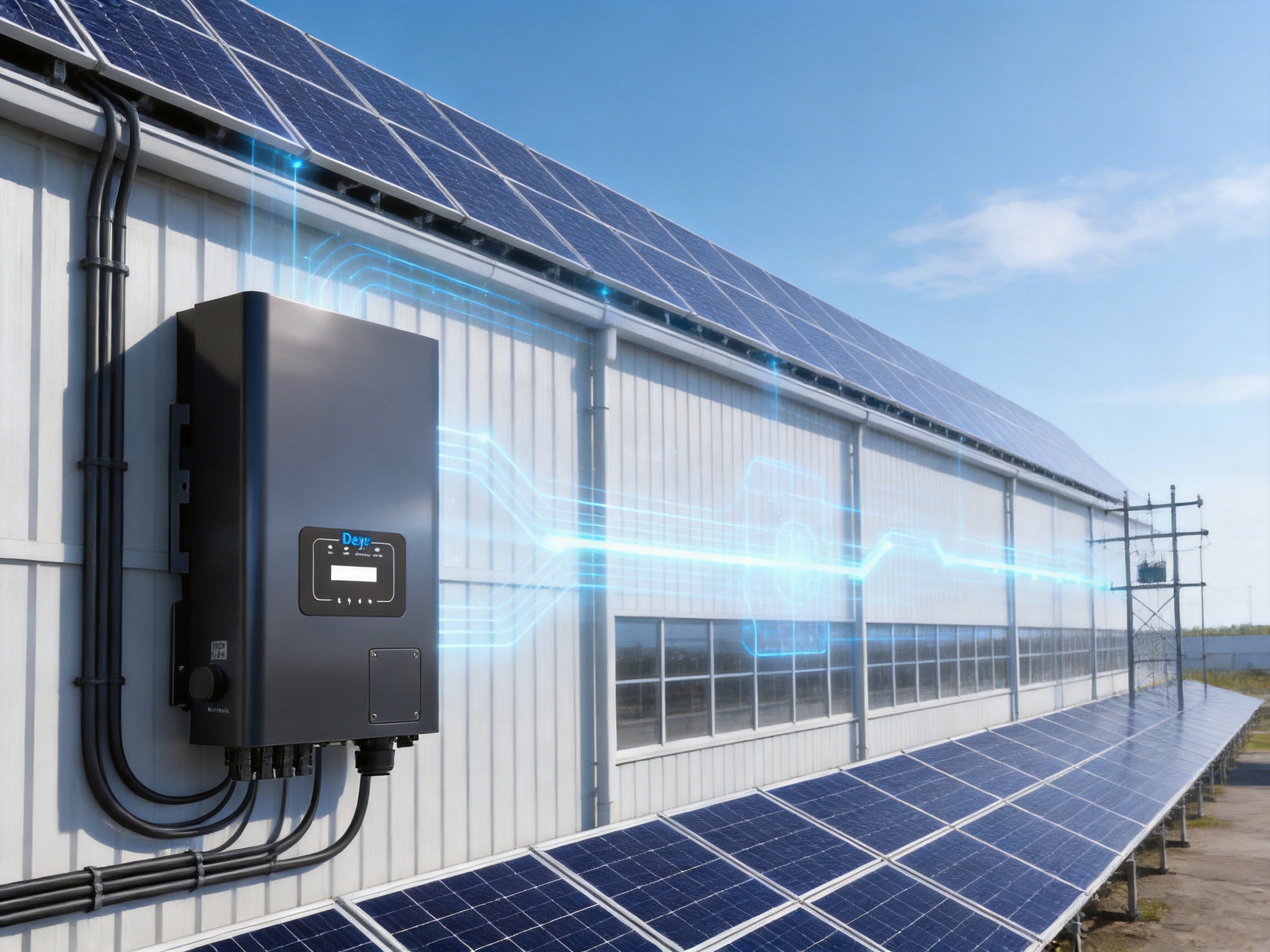
Protection and Operational Safety
Safety is a central requirement for commercial PV equipment. The SUN-18/20/22/23/25K-G06P3-EU-AM2 series includes a broad range of electrical and operational protection functions designed to reduce risk to the inverter, PV array, connected equipment, and personnel.
DC-Side Protection
DC reverse polarity protection helps prevent damage when PV conductors are connected incorrectly. This function is particularly valuable during installation and maintenance, when multiple strings may be handled in a confined work area. It does not replace careful polarity verification before energization, but it adds a further layer of protection.
Insulation impedance detection monitors the relationship between the DC circuit and earth. Abnormal insulation conditions can indicate damaged cables, moisture ingress, connector problems, or module-related faults. Early detection can help prevent unsafe operating conditions and assist technicians in troubleshooting.
DC component monitoring is included to identify unwanted direct-current components associated with inverter operation. The product also includes a DC switch, allowing the DC side to be isolated according to the installation and service procedure.
Type II DC surge protection is provided to help manage transient overvoltage events. Surge protection is especially relevant for rooftop systems exposed to electrical disturbances or indirect lightning effects. The complete protection strategy should also consider building-level surge protection, grounding, cable routing, and local regulations.
AC-Side Protection
AC output overcurrent protection, overvoltage protection, and short-circuit protection are integrated into the design. These functions help safeguard the inverter and connected AC network against abnormal conditions. Anti-islanding protection is also provided, ensuring that the inverter can respond appropriately when the utility grid is unavailable.
Residual current detection helps identify leakage-current conditions. Combined with correct protective-earthing arrangements and properly selected external protection devices, this function contributes to the electrical safety of the installation.
Type II AC surge protection is included alongside the DC protection. The dual-sided arrangement recognizes that transient events can affect both the PV input and grid output circuits. A qualified electrical professional should determine whether additional surge protective devices are required based on the site’s lightning protection system and local installation rules.
Optional AFCI and Anti-PID Functions
An arc fault circuit interrupter is available as an option. Arc faults can occur when damaged conductors, loose terminations, degraded connectors, or insulation defects generate localized electrical arcing. AFCI technology can help identify characteristic arc signatures and interrupt the circuit before a more serious event develops, subject to the final product configuration and applicable requirements.
The anti-PID function is also optional. Potential-induced degradation can reduce PV module performance under certain system voltage, environmental, and module-construction conditions. An anti-PID solution may help address this risk in applications where the module technology and project environment make PID a concern. The final selection should be made in coordination with the module supplier and project engineer.
Grid Support and Energy Management Functions
Solar installations are increasingly expected to support the grid rather than simply inject power whenever sunlight is available. The inverter’s adjustable power factor range, zero-export capability, and VSG application support make it suitable for more advanced energy management strategies.
Zero-export operation is useful for facilities whose interconnection agreement does not permit energy export. In this arrangement, an energy meter or compatible control system measures the site’s consumption and adjusts inverter output so that PV production remains aligned with local demand. The implementation requires suitable metering, correct communications, and careful commissioning.
VSG application support can be relevant in systems that require behavior similar to a synchronous generator. Such functionality may contribute to voltage or frequency support in suitable power-system configurations. The exact behavior depends on firmware, system architecture, grid requirements, and the selected operating mode. Engineers should confirm compatibility before using the product in advanced grid-support applications.
The power factor adjustment range from 0.8 leading to 0.8 lagging gives the inverter additional control over reactive power. This can help comply with utility requirements and address voltage behavior in distribution networks. Reactive power control should be coordinated with the site’s electrical equipment because it can affect current, apparent power, and voltage regulation.
Monitoring and Communications
Reliable monitoring is essential for maintaining solar asset performance. The inverter includes an LCD1602 display and supports RS485, RS232, WiFi, and LAN communication interfaces. These options allow the equipment to be integrated into different monitoring arrangements, from local commissioning tools to networked commercial energy platforms.
RS485 is widely used in industrial environments because it can support communication over practical distances and in electrically demanding settings when installed correctly. LAN connectivity can support connection to a local network, while WiFi can simplify communication in suitable locations. RS232 may be used for specific service, commissioning, or accessory interfaces.
String intelligent monitoring is available as an option. String-level information can help operators identify underperforming strings, abnormal current behavior, or developing faults. This is particularly valuable in large commercial systems where a visual inspection of every module and cable would be time-consuming.
Monitoring improves more than fault detection. Historical operating data can help asset owners compare daily production, identify seasonal changes, verify system commissioning, and plan preventive maintenance. When combined with site consumption data, monitoring can also show how effectively the PV system is reducing grid purchases.
Communication equipment should be installed with appropriate attention to cybersecurity, network segmentation, password management, and access control. Monitoring convenience should not compromise the security of the plant’s operational data or connected systems.
Mechanical Construction and Environmental Suitability
The inverter has an IP65 ingress protection rating. This indicates that the enclosure is designed to protect internal components against dust ingress and water projected from applicable directions under standardized test conditions. IP65 does not mean that the inverter can be submerged or installed without regard to drainage, condensation, or direct environmental exposure.
The product is rated for operation from -25°C to +60°C and for ambient humidity from 0% to 100%, subject to the manufacturer’s installation conditions and derating requirements. The permissible altitude is up to 4000 meters. High-altitude installations require careful review because reduced air density can affect heat dissipation and may require power derating or other design considerations.
The cabinet measures 283 by 525 by 224 millimeters, excluding connectors and mounting brackets. Its listed weight is 12.7 kg or 16 kg depending on the model and configuration. These dimensions and weights support relatively manageable handling compared with many larger commercial conversion units, while still providing the electrical capacity required for three-phase applications.
The non-isolated topology is common in modern transformerless PV inverters and can support high conversion efficiency and reduced equipment size. Because the topology is non-isolated, system designers must carefully verify grounding, insulation monitoring, module compatibility, and local electrical requirements.
The overvoltage category is specified as OVC II on the DC side and OVC III on the AC side. These classifications assist engineers in coordinating insulation, surge protection, and installation conditions within the broader electrical system.
Installation Considerations
The selected mounting location should provide adequate structural support, ventilation, service access, and protection from unnecessary heat or contamination. The inverter should not be placed where water can collect, where air circulation is restricted, or where maintenance personnel cannot safely access the connection and display areas.
DC and AC cable routing should be organized to minimize mechanical stress and electromagnetic interference. Connectors must be compatible, correctly crimped, fully engaged, and protected from tension. All external circuit breakers, isolators, surge devices, and earthing arrangements should be selected according to the inverter ratings and local regulations.
Before commissioning, the installer should verify string polarity, open-circuit voltage, insulation resistance, conductor sizing, torque values, AC phase sequence, protective-earth continuity, communications settings, and grid-code configuration. These checks help reduce startup faults and provide a reliable baseline for future maintenance.
Advantages in Comparison with Conventional Alternatives
The product’s competitive value comes from the combination of several features rather than from one isolated specification. A commercial inverter may have high efficiency but limited communications, or broad voltage compatibility but insufficient protection functions. This series brings together flexible PV input design, dual MPPT control, efficient conversion, advanced grid functions, and a comprehensive protection package.
Compared with Single-MPPT Designs
Inverters with only one MPPT channel may be suitable for uniform arrays, but they can be less flexible when a roof contains multiple orientations or unavoidable shading differences. The two-MPPT structure of this series allows the designer to separate array sections and reduce the effect of mismatched operating conditions.
This does not eliminate the need for good engineering. The best results still come from grouping similar modules and orientations together. However, the additional tracker provides more practical design options and may reduce the compromises required during rooftop planning.
Compared with Lower-Voltage Commercial Inverters
Some commercial inverter platforms have lower maximum DC voltage limits, which can restrict string length and affect cable planning. With a maximum PV input voltage of 1100 V and an MPPT range reaching 1000 V, this series supports a broad string design envelope. Longer strings may help reduce the number of parallel conductors and simplify some array layouts.
The benefit must be evaluated against local code, module specifications, temperature conditions, and installation practice. Nevertheless, the high-voltage input design offers system designers greater flexibility than many lower-voltage alternatives.
Compared with Basic Grid-Tied Inverters
Basic grid-tied inverters may focus mainly on DC-to-AC conversion. This series adds zero-export support, VSG application capability, adjustable power factor, optional string monitoring, and multiple communication interfaces. These functions make it more adaptable to energy management and grid-support requirements.
Commercial customers increasingly want visibility into their energy assets and greater control over self-consumption. The product’s communications and control options are therefore relevant to the complete project value, not merely to the inverter’s conversion stage.
Compared with Larger Centralized Units
A centralized inverter may be efficient for very large and uniform PV fields, but distributed string inverters can offer advantages where the site includes multiple roof sections, complicated cable routes, or different operating conditions. Using several units can simplify phased construction and allow faults to be localized to a smaller portion of the plant.
The 18 kW to 25 kW range is well suited to distributed commercial architecture. It offers enough capacity for substantial systems while avoiding the need to place all conversion equipment in one central location. Project developers should compare total installed cost, maintenance strategy, cable design, and energy yield rather than selecting an architecture based on inverter price alone.
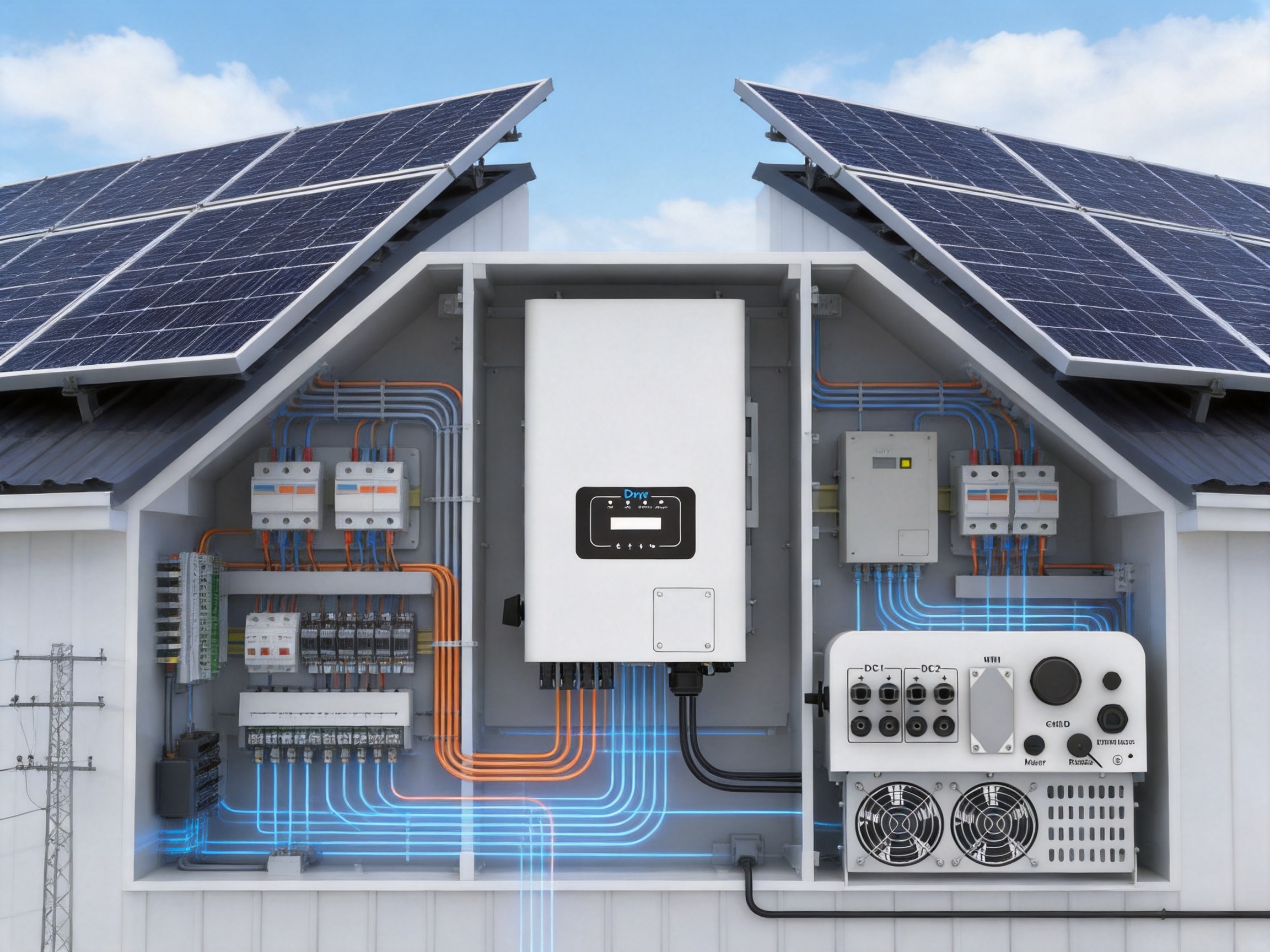
Manufacturing Strength and Quality Approach
Ningbo Deye Inverter Technology Co., Ltd. was founded in 2000 and integrates research and development, product design, manufacturing, sales, and service. This vertically coordinated structure can support faster communication between engineering, production, quality, and customer-service teams. It also enables product improvements to be informed by field experience and application feedback.
The company operates across photovoltaic inverters, energy storage systems, microinverters, environmental appliances, and related energy technologies. Its product portfolio includes string inverters from 1 kW to 136 kW, energy storage inverters from 3 kW to 80 kW, and microinverters from 300 W to 2.2 kW. This broad portfolio creates an engineering foundation that spans residential, commercial, industrial, and utility-scale applications.
Manufacturing capability is particularly important for inverter products because quality depends on more than circuit design. It requires controlled component procurement, accurate automated assembly, reliable soldering, careful thermal-interface application, enclosure sealing, firmware management, calibration, and comprehensive end-of-line testing.
Research and Development Integration
An integrated R&D organization can coordinate power electronics, embedded software, grid control, mechanical engineering, thermal design, communications, and protection technology. For a product such as the SUN-18/20/22/23/25K-G06P3-EU-AM2, these disciplines must work together. The MPPT algorithms must coordinate with the DC input stage, the grid-control software must respond to voltage and frequency conditions, and the protection system must operate without compromising normal energy production.
Continuous development is also needed to maintain compatibility with changing grid regulations. The inverter lists support for several grid and safety standards, including IEC 61727, IEC 62116, CEI 0-21, EN 50549, NRS 097, RD 140, UNE 217002, OVE-Richtlinie R25, G99, and VDE-AR-N 4105. Compliance with a specific national requirement depends on the exact model configuration, firmware, certification status, and installation conditions.
Production Process Control
A high-quality inverter manufacturing process normally begins with incoming inspection of electronic components, power semiconductors, capacitors, magnetic components, connectors, fans, circuit boards, and enclosure parts. Traceability is important because it allows production teams to identify component batches and investigate quality trends.
Printed circuit board assembly requires accurate component placement, controlled soldering profiles, inspection of solder joints, and verification of polarity-sensitive components. Power conversion boards must be manufactured with particular attention to creepage distances, clearance, thermal paths, and mechanical stability.
Mechanical assembly includes the installation of heat dissipation structures, cooling components, protective barriers, cable interfaces, and enclosure seals. Correct torque and connector engagement are essential because loose connections can create heat, intermittent operation, or arc-fault risks. Enclosure assembly must preserve the intended IP65 protection level when all covers, glands, connectors, and service panels are correctly installed.
Firmware loading and configuration are also controlled manufacturing steps. The inverter’s MPPT behavior, grid response, protection thresholds, communications functions, display operation, and optional features depend on coordinated hardware and software. Each unit should be configured and tested according to its model rating and market requirements.
Testing and Reliability Verification
End-of-line testing may include insulation resistance testing, dielectric withstand testing, grounding continuity verification, DC input simulation, AC output testing, efficiency checks, communication checks, display verification, protective-function simulation, and thermal or load testing. These procedures help identify manufacturing defects before equipment leaves the factory.
Reliability verification can also include environmental stress testing, vibration testing, temperature cycling, humidity exposure, and repeated startup and shutdown tests. Such evaluation is important because solar inverters operate outdoors for many years and experience daily changes in temperature, load, irradiance, and grid conditions.
Quality management does not end when the inverter is shipped. Field-service data, warranty analysis, installer feedback, and monitoring information can reveal improvement opportunities. A manufacturer with its own R&D, production, sales, and service organization is better positioned to connect these data sources and implement corrective actions across future production batches.
Standards, Compliance, and Responsible Deployment
The product lists grid regulations and safety EMC standards covering multiple markets. The stated safety and electromagnetic compatibility standards include IEC/EN 61000-6-1/2/3/4, IEC/EN 62109-1, and IEC/EN 62109-2. These standards relate to electromagnetic compatibility and the safety of power converters used in photovoltaic systems.
Standards compliance helps establish a technical baseline, but it is not a substitute for site-specific engineering. The installer remains responsible for confirming that the selected inverter, firmware version, protective equipment, wiring, earthing, disconnects, and commissioning settings satisfy the requirements of the local utility and authority having jurisdiction.
Grid connection documents should be reviewed before procurement. Particular attention should be given to voltage and frequency response, reactive power settings, anti-islanding requirements, export limitations, communications protocols, and requirements for external protection. Projects involving zero export or VSG operation may require additional metering, control equipment, or utility approval.
Responsible deployment also includes safe working procedures. Only trained and authorized personnel should install, commission, or service the inverter. PV arrays can generate hazardous DC voltage whenever illuminated, even when the AC grid is disconnected. Correct isolation, lockout, verification, personal protective equipment, and manufacturer procedures are essential.
System Design Guidance
PV String Design
Designers should begin with the electrical characteristics of the selected PV module. The maximum open-circuit voltage at the lowest expected temperature must remain below the inverter’s maximum PV input voltage. The string operating voltage should remain within the MPPT range across expected temperature conditions. The combined short-circuit and operating currents of parallel strings must remain within the relevant input limits.
Array sections with similar orientation, tilt, module type, and shading conditions should generally be assigned to the same MPPT channel. When different array characteristics are connected to one tracker, mismatch losses may increase. The two-tracker design makes it easier to organize the array logically and maintain consistent electrical behavior.
PV oversizing should be modeled using local solar irradiation data and expected clipping. An array that is too small may leave the inverter underutilized for much of the year, while an excessively large array may increase clipping and installation cost. The listed maximum PV input power provides an upper boundary, not a universal recommendation for every project.
AC System Design
AC cable sizes should be selected based on current, voltage drop, installation method, ambient temperature, grouping, and local code. Circuit breakers and disconnect devices must be coordinated with the inverter’s rated and maximum output currents. The three-phase connection requires correct phase identification and reliable protective-earth bonding.
Where multiple inverters are installed, the distribution board should account for aggregate current, fault levels, selectivity, surge protection, and maintenance isolation. The design should also consider the utility transformer, site loads, power factor requirements, and possible export control.
Monitoring and Commissioning
Monitoring architecture should be defined before installation. The project team should decide whether to use RS485, RS232, WiFi, LAN, or a combination of interfaces. Communication cables should be routed and terminated according to the applicable protocol requirements. Network settings should be documented so that future service personnel can understand the system configuration.
Commissioning should include a review of the inverter model, firmware, grid profile, date and time, communication address, export-control settings, and reactive power parameters. Production data should be compared with expected conditions after startup. Unexpectedly low output may result from shading, string mismatch, incorrect configuration, high temperature, grid limitations, or a communications problem.
Maintenance and Lifecycle Benefits
Preventive maintenance helps preserve energy yield and reduces unplanned downtime. Maintenance tasks may include visual inspection, checking cable and connector condition, verifying mounting security, cleaning air inlets and outlets, reviewing fault records, confirming communication status, and inspecting surge protection indicators where provided.
Monitoring data can assist with condition-based maintenance. Repeated alarms, unusual temperature behavior, inconsistent string currents, or communication interruptions may indicate a developing issue. Addressing problems early can reduce the risk of extended production loss.
The common platform across five power ratings can simplify spare-parts planning for operators managing several projects. Technicians familiar with one model can more easily work on the other models in the family, although all service procedures must follow the exact model documentation.
The listed standard warranty is five years. Warranty conditions, registration requirements, regional service arrangements, and exclusions should be confirmed before purchase. A complete lifecycle assessment should include technical support, availability of replacement components, firmware management, installer training, and service response procedures.
Technical Specification Summary
| Specification | 18K | 20K | 22K | 23K | 25K |
|---|---|---|---|---|---|
| Maximum PV input power | 27 kW | 30 kW | 33 kW | 34.5 kW | 37.5 kW |
| Maximum PV input voltage | 1100 V | 1100 V | 1100 V | 1100 V | 1100 V |
| Startup voltage | 150 V | 150 V | 150 V | 150 V | 150 V |
| MPPT voltage range | 200–1000 V | 200–1000 V | 200–1000 V | 200–1000 V | 200–1000 V |
| Rated PV input voltage | 600 V | 600 V | 600 V | 600 V | 600 V |
| Rated AC active power | 18 kW | 20 kW | 22 kW | 23 kW | 25 kW |
| Maximum AC apparent power | 19.8 kVA | 22 kVA | 24.2 kVA | 25.3 kVA | 27.5 kVA |
| Maximum efficiency | 98.2% | 98.2% | 98.2% | 98.2% | 98.2% |
| European efficiency | 97.7% | 97.7% | 97.7% | 97.7% | 97.7% |
| MPPT efficiency | >99% | >99% | >99% | >99% | >99% |
| MPPT trackers and strings | 2 / 2+2 | 2 / 2+2 | 2 / 2+2 | 2 / 2+2 | 2 / 2+2 |
| Ingress protection | IP65 | IP65 | IP65 | IP65 | IP65 |
| Operating temperature | -25°C to +60°C | -25°C to +60°C | -25°C to +60°C | -25°C to +60°C | -25°C to +60°C |
| Warranty | 5 years | 5 years | 5 years | 5 years | 5 years |
Company Resources and Global Experience
Ningbo Deye Inverter Technology Co., Ltd. has developed a broad international presence, with products sold in more than 140 countries and regions. This global exposure gives the company experience with diverse climates, grid structures, installer practices, and regulatory environments.
The company’s activities extend beyond individual inverter products. Its portfolio includes photovoltaic inverters, energy storage systems, microinverters, energy management technologies, residential all-in-one systems, commercial and industrial battery cabinets, modular energy storage systems, PV-battery-EV charging solutions, and utility-scale liquid-cooled storage systems.
This broader capability can benefit customers planning an energy transition in stages. A commercial site may begin with a grid-connected PV system and later add energy storage, EV charging, or advanced load management. A supplier with experience across these categories can help reduce integration complexity, although every project still requires a detailed compatibility review.
The company also supports an energy Internet of Things ecosystem based on cloud monitoring and wireless energy management technologies. These capabilities complement the inverter’s local communication interfaces by enabling broader visibility across distributed assets when the relevant monitoring equipment and services are selected.
Its public-company status since listing on the Shanghai Stock Exchange in April 2021 also reflects a significant organizational scale. For equipment buyers, scale can support investment in research, manufacturing capacity, certification, technical service, and supply-chain management. Project owners should nevertheless evaluate the exact regional support structure and contractual terms for each purchase.
Frequently Asked Questions
What type of inverter is this product?
It is a three-phase grid-connected string inverter series with five rated power options: 18 kW, 20 kW, 22 kW, 23 kW, and 25 kW. It is intended primarily for commercial and industrial photovoltaic installations.
How many MPPT trackers does the inverter have?
Each model has two MPP trackers, with two strings per tracker according to the stated configuration. This supports PV arrays with different orientations or operating conditions.
What is the maximum PV input voltage?
The maximum PV input voltage is 1100 V. The startup voltage is 150 V, and the MPPT voltage range is 200 V to 1000 V.
Can the inverter be connected to a larger PV array than its AC rating?
Yes. The listed maximum PV input power is higher than the rated AC output for every model, ranging from 27 kW for the 18 kW model to 37.5 kW for the 25 kW model. The final DC-to-AC ratio must be calculated using module specifications, local climate, voltage limits, current limits, and expected clipping.
Does the product support zero export?
Yes. Zero-export application support is listed among the product features. A complete zero-export system normally requires compatible metering and control equipment, correct configuration, and compliance with local utility requirements.
What does VSG application support mean?
VSG means virtual synchronous generator. The function can support grid-oriented operating strategies that emulate certain characteristics of synchronous generation. The actual application depends on the system architecture, firmware, grid code, and project approval.
What is the maximum efficiency?
The maximum efficiency is up to 98.2%. The stated European efficiency is 97.7%, and MPPT efficiency is greater than 99%.
What protection functions are included?
Protection functions include DC reverse polarity protection, AC output overcurrent protection, AC output overvoltage protection, AC short-circuit protection, thermal protection, insulation impedance detection, DC component monitoring, anti-islanding protection, residual current detection, a DC switch, and Type II surge protection on both the DC and AC sides. AFCI and anti-PID functions are listed as optional.
Is the inverter suitable for outdoor installation?
The inverter has an IP65 enclosure rating and an operating temperature range of -25°C to +60°C, with derating above 45°C. Outdoor installation suitability depends on correct mounting, clearance, ventilation, cable sealing, environmental conditions, and compliance with the installation manual.
What communications interfaces are available?
The product supports RS485, RS232, WiFi, and LAN interfaces. String intelligent monitoring is available as an optional function.
What grid voltages does the inverter support?
The stated rated output voltage is 220/380 V and 230/400 V, with a voltage range of 0.85Un to 1.1Un in a three-phase, neutral, and protective-earth configuration.
Can the inverter provide reactive power control?
Yes. The power factor adjustment range is specified as 0.8 leading to 0.8 lagging. The final reactive power settings should be coordinated with the grid operator and the site’s electrical design.
What warranty is provided?
The listed warranty is five years. Buyers should confirm the warranty terms, registration process, regional service arrangements, and applicable conditions before final procurement.
What should be checked before installation?
Installers should verify PV string voltage, current, polarity, insulation, cable sizing, grounding, AC protection, grid voltage and frequency, mounting conditions, communications requirements, and local grid-code settings. All work should be performed by qualified personnel.
Conclusion
The SUN-18/20/22/23/25K-G06P3-EU-AM2 series is a flexible three-phase string inverter platform for commercial and industrial solar applications. Its principal strengths include five selectable power ratings, two MPP trackers, a 1100 V maximum PV input voltage, a 200–1000 V MPPT range, high conversion efficiency, broad AC compatibility, adjustable power factor, zero-export support, VSG application capability, and extensive built-in protection.
The product compares favorably with simpler inverter designs because it combines energy harvesting, grid support, monitoring, and safety functions in one compact platform. Its IP65 enclosure, intelligent air cooling, high-altitude operating capability, and wide temperature range support deployment across diverse environments when the installation is properly engineered.
The manufacturer’s integrated R&D, design, production, sales, and service structure adds further value. Experience across string inverters, microinverters, energy storage, EV charging, and energy management allows the company to address complete solar and energy-system requirements rather than a single conversion stage.
For system designers, the key to achieving the best result is correct application. PV strings must be sized within voltage and current limits, AC equipment must be coordinated with the inverter rating, communications and export controls must be planned in advance, and all grid and safety requirements must be verified. When these principles are followed, the inverter family provides a scalable foundation for efficient, intelligent, and dependable three-phase solar generation.

References
1. SUN-18-25K-G06P3-EU-AM2 Product Datasheet, technical specification document.
2. SUN-18-25K-G06P3-EU-AM2 Installation and Operation Manual.
3. IEC 62109-1, Safety of Power Converters for Use in Photovoltaic Power Systems, General Requirements.
4. IEC 62109-2, Safety of Power Converters for Use in Photovoltaic Power Systems, Particular Requirements for Inverters.
5. IEC 61727, Photovoltaic Systems: Utility Interface Characteristics.
6. IEC 62116, Utility-Interconnected Photovoltaic Inverters: Test Procedure of Islanding Prevention Measures.
7. IEC/EN 61000 Series, Electromagnetic Compatibility Requirements.
8. EN 50549, Requirements for the Connection of Generators in Parallel with Public Distribution Networks.
9. Manufacturer-provided product and company information supplied for this article.
Product: SUN-18/20/22/23/25K-G06P3-EU-AM2

PREV:High-Voltage Three-Phase Hybrid Inverter for Scalable Solar Energy Storage
NEXT:Compact All-in-One Energy Storage for Flexible Solar Power
Share
Product recommendations
news recommendations
-
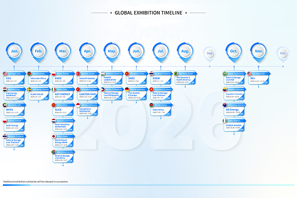 GLOBAL EXHIBITION TIMELINE
*Click to view larger image
-
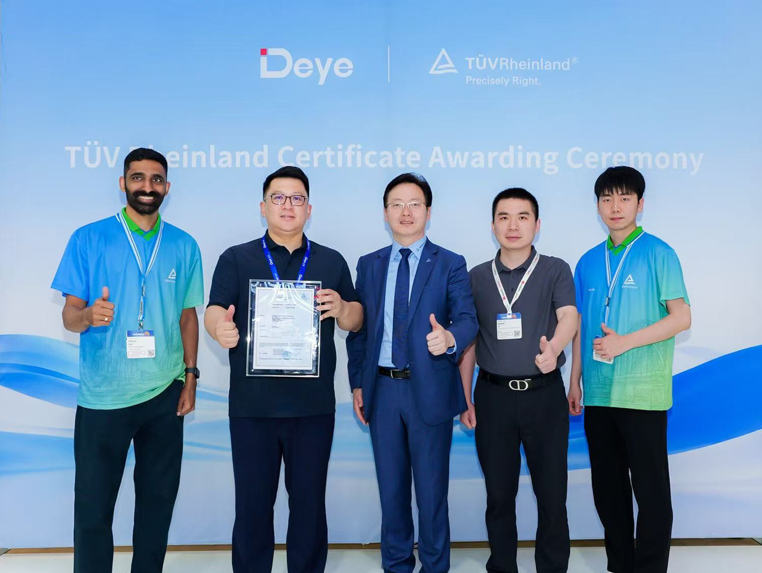 Deye Secures Multiple TÜV Rheinland Certifications at The smarter E Europe
On June 23, the opening day of The smarter E Europe 2026, Deye was officially awarded several presti...
-
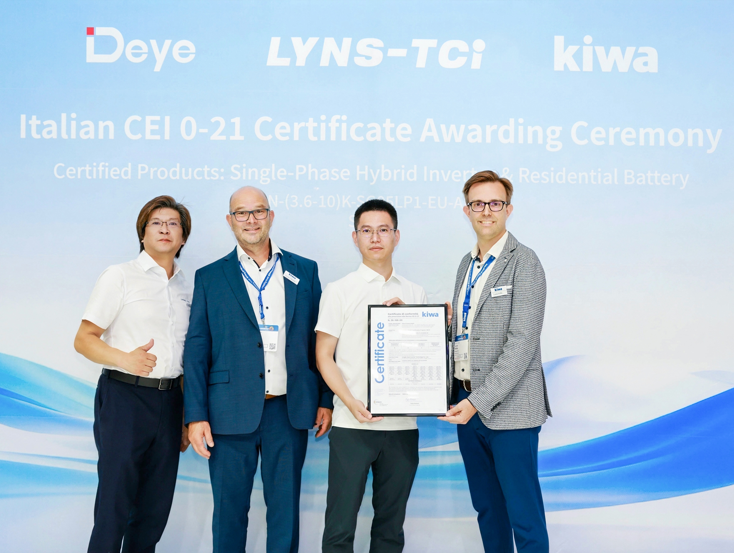 Deye Next-Gen Residential Energy Storage Products Receive Italian CEI 0-21 Certification from Kiwa
At The smarter E Europe 2026, Deye, a leading supplier of inverters and energy storage solutions, of...

Copyright@ 2024.Ningbo Deye Inverter Technology Co.,Ltd. All rights reserved. Solar Inverter Manufacturer
