
 Online Shop
 English
 China - 简体中文
 Global - English
 Brazil - Português
 Netherlands - Dutch
 Italy - Italiano
 Germany - Deutsch
 Spain - Español
 France - Français
 Vietnam - Tiếng Việt
 Poland - Polski
 Australia - English
 Japan - 日本語
Blog

High-Capacity Single-Phase Hybrid Inverter for Flexible Solar and Battery Storage
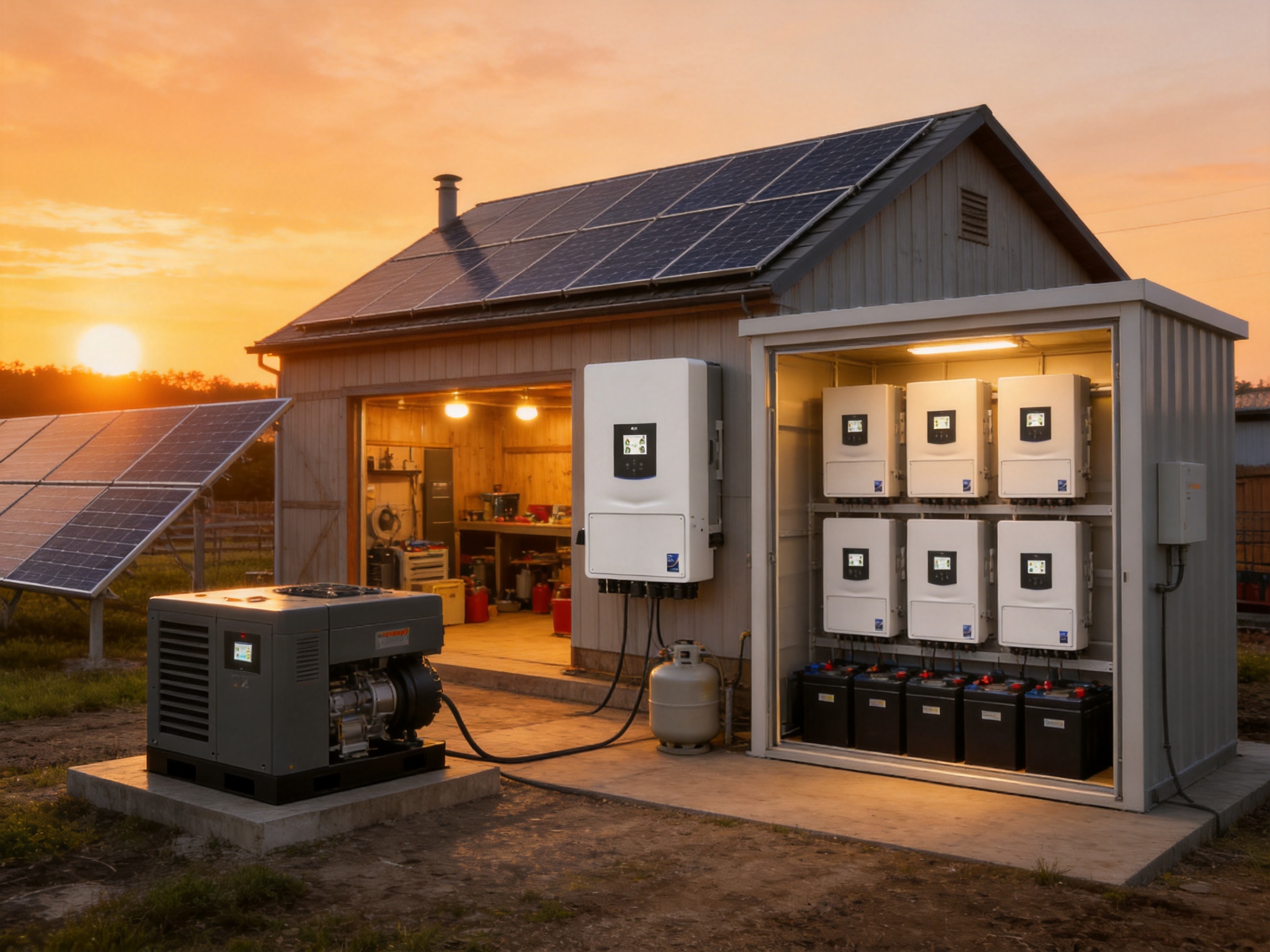
The transition from conventional electricity supply to distributed solar energy is accelerating across homes, small businesses, farms, workshops, and light commercial properties. As electricity prices change, grid reliability becomes more important, and battery storage becomes more affordable, users increasingly need an inverter that can do more than convert direct current into alternating current. A modern energy system must manage solar generation, batteries, the utility grid, backup loads, and, in some cases, a diesel generator.
The SUN-7/7.6/8/10/12K-SG06LP1-EU-CM3 series is designed for this wider role. It is a single-phase low-voltage hybrid inverter family with five power options: 7 kW, 7.6 kW, 8 kW, 10 kW, and 12 kW. The series combines three maximum power point trackers, low-voltage battery compatibility, high battery charging and discharging capability, AC coupling, parallel operation, and support for both grid-connected and off-grid applications.
Rather than serving only as a solar inverter, the product functions as an energy management platform. It can use photovoltaic power directly, store surplus energy in a 40–60 V battery system, discharge that battery when solar production is low, pass grid power to loads, and provide backup power during an outage. It can also store energy supplied by a diesel generator, making the system suitable for locations where generator support remains essential.
The design is especially relevant to users who want to retrofit an existing solar installation, expand battery capacity over time, or create a scalable backup system. Its high current capability, multiple operating modes, and parallel architecture help it compete with conventional grid-tie inverters, basic battery inverters, and smaller hybrid units that cannot support comparable loads or system configurations.
Product Overview
The product family belongs to the single-phase low-voltage hybrid inverter category. It is available in five rated power classes, allowing system designers to select a capacity that is closer to the actual load profile rather than oversizing every installation.
| Model | Rated Active Power | Maximum PV Access Power | Maximum Charging and Discharging Current | Maximum AC Input/Output Apparent Power |
|---|---|---|---|---|
| SUN-7K-SG06LP1-EU-CM3 | 7,000 W | 14,000 W | 175 A | 7,700 VA |
| SUN-7.6K-SG06LP1-EU-CM3 | 7,600 W | 15,200 W | 185 A | 8,360 VA |
| SUN-8K-SG06LP1-EU-CM3 | 8,000 W | 16,000 W | 185 A | 8,800 VA |
| SUN-10K-SG06LP1-EU-CM3 | 10,000 W | 20,000 W | 220 A | 11,000 VA |
| SUN-12K-SG06LP1-EU-CM3 | 12,000 W | 24,000 W | 250 A | 13,200 VA |
All models support lead-acid or lithium-ion batteries within a nominal voltage range of 40–60 V. Lithium battery charging is self-adaptive to the battery management system, helping the inverter coordinate with compatible battery packs. One battery input is provided, while multiple batteries can be connected in parallel when the system design and battery manufacturer requirements permit it.
The series has a maximum DC input voltage of 500 V, a start-up voltage of 125 V, and an MPPT operating range of 150–425 V. Its rated DC input voltage is 370 V. These values provide a broad operating window for photovoltaic string design while maintaining compatibility with many common module configurations.
The enclosure measures 340 × 580 × 234 millimeters, excluding connectors and mounting brackets. A compact enclosure is valuable in residential utility rooms, garages, plant rooms, and small commercial electrical spaces where wall area is limited. The product weighs approximately 24.6–24.9 kilograms depending on the model.
Why Hybrid Architecture Matters
A conventional grid-tie inverter generally sends solar energy to the grid or to local loads while the grid is available. If the grid fails, many standard grid-tie systems shut down for safety reasons. They may also require an additional battery inverter and control equipment if the owner later wants backup operation.
A hybrid inverter is designed to coordinate several energy sources and destinations in one system. Solar power can supply loads first, charge batteries with surplus energy, or be exported to the grid according to programmed settings. Battery energy can be reserved for outages, used during high-price periods, or discharged according to a daily schedule. Grid and generator sources can supplement the system when solar and battery capacity are insufficient.
This integrated approach can reduce the complexity of an energy storage installation. Instead of combining several separate power conversion devices, the installer can use one central inverter platform with dedicated control logic and communication interfaces. Fewer major conversion stages can simplify commissioning, reduce cabinet space, and make system monitoring more straightforward.
The inverter also supports AC coupling for retrofitting an existing solar system. This is a major advantage for property owners who already have a grid-tie solar installation but now want battery storage. In a retrofit application, the existing solar inverter can remain in service while the hybrid inverter manages the battery, backup loads, and energy exchange on the AC side. This can reduce the need to replace functioning equipment and may lower the total project cost.
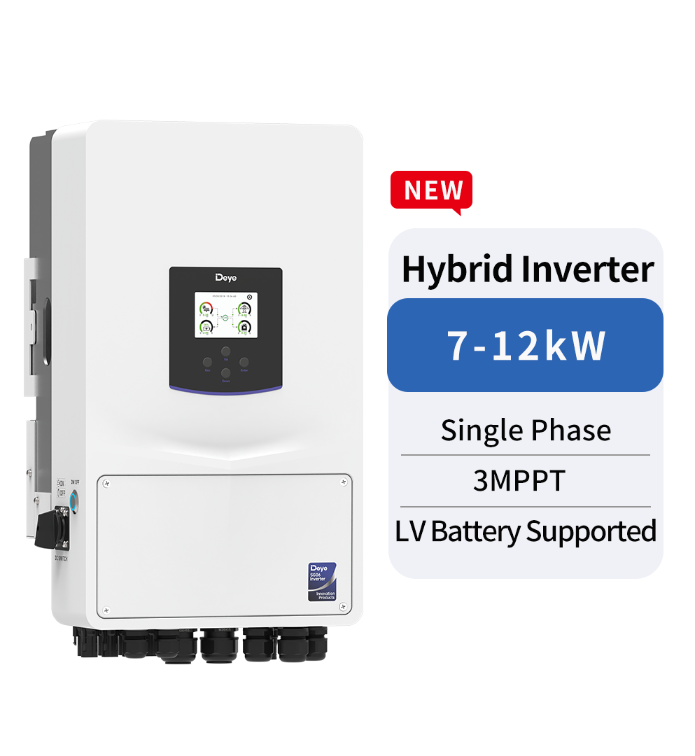
SUN-7/7.6/8/10/12K-SG06LP1-EU-CM3
High Battery Power for Low-Voltage Storage
Low-voltage battery systems remain popular because they are widely available, relatively easy to scale, and compatible with many residential and small commercial storage products. However, high-power operation at low battery voltage requires substantial current. This is where the product family distinguishes itself from many smaller hybrid inverters.
The 7 kW model supports a maximum charging and discharging current of 175 A. The 7.6 kW and 8 kW models support 185 A. The 10 kW model reaches 220 A, while the 12 kW model supports up to 250 A. This high-current architecture allows the inverter to extract more usable power from a 40–60 V battery bank without requiring a high-voltage battery platform.
For example, a low-voltage battery operating near 50 V must deliver approximately 200 A to supply 10 kW before conversion losses are considered. The ability to manage such current is important for users who want substantial backup power from low-voltage storage. It also supports stronger load management during periods when photovoltaic production is unavailable.
Low-voltage compatibility can provide practical benefits in battery selection. Installers may have access to a broader range of batteries, and system owners may be able to add parallel battery modules as energy requirements grow. Battery selection must always follow the battery manufacturer’s current limits, communication requirements, protection instructions, and installation rules, but the inverter’s current capability provides a strong foundation for high-power low-voltage systems.
The inverter supports lithium-ion batteries with self-adaptive charging control through the battery management system. This communication-based approach is important because lithium batteries require accurate control of voltage, current, temperature, state of charge, and protection status. When a compatible BMS connection is established, the inverter can respond to battery information rather than relying only on fixed charging assumptions.
Lead-acid battery support further broadens the product’s application range. Lead-acid technology remains relevant in backup installations, remote sites, agricultural facilities, and markets where established battery supply chains influence project decisions. The ability to work with both battery chemistries gives system designers more flexibility during procurement and replacement planning.
Three MPPTs for More Flexible Solar Design
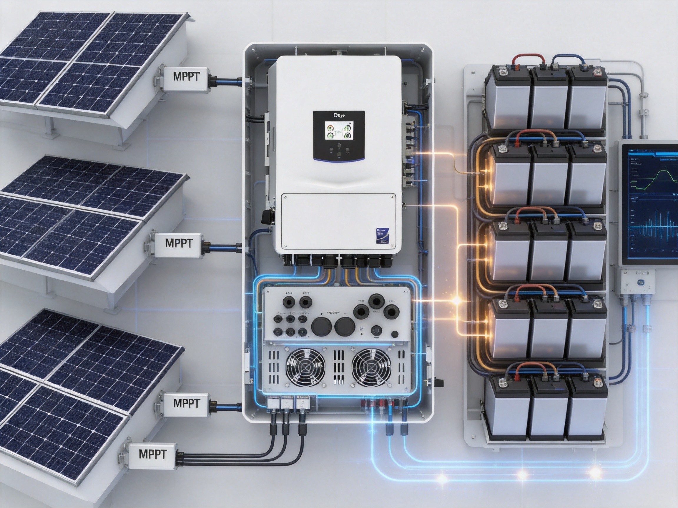
The photovoltaic input stage includes three maximum power point trackers. MPPT technology continuously adjusts the operating point of a solar string so that the array can produce as much power as conditions allow. This is especially valuable when module temperature, shading, orientation, or roof geometry varies across the installation.
The three-tracker arrangement supports two string configurations depending on the model group. The published data identifies configurations of three trackers with either two plus one plus one strings or two plus two plus one strings. This enables the installer to distribute photovoltaic strings across independent tracking channels instead of forcing all arrays to operate at the same voltage and current conditions.
The maximum operating PV input current is specified as 36 + 18 + 18 A for one configuration and 36 + 36 + 18 A for the other. Maximum short-circuit current is specified as 54 + 27 + 27 A or 54 + 54 + 27 A, respectively. These ratings should be checked carefully against the electrical characteristics of the selected modules and the final string design.
Three MPPTs can be advantageous on roofs with different orientations. For example, one tracker may serve a south-facing array, another may serve an east-facing array, and the third may serve a west-facing array. The arrangement can also help separate strings with different tilt angles or partially different shading patterns.
Compared with a single-MPPT inverter, the product can reduce the compromise between differently performing array sections. Compared with some two-MPPT designs, the third tracker may give installers more freedom when dealing with complex roof layouts, multiple buildings, or phased solar expansion.
The MPPT voltage range of 150–425 V provides a useful operating window, while the 125 V start-up voltage allows the inverter to begin operation when the PV array reaches the required level. The maximum DC input voltage is 500 V, and system designers must maintain adequate safety margins for the lowest and highest expected environmental temperatures.
Oversizing the PV Array for Better Energy Yield
The product series permits substantial photovoltaic oversizing relative to nominal AC output. Maximum PV access power ranges from 14 kW for the 7 kW model to 24 kW for the 12 kW model. Maximum DC input power ranges from 11.2 kW to 19.2 kW across the series.
PV oversizing is useful because a solar array rarely operates at its nameplate output for an entire day. Factors such as cloud cover, module temperature, dust, wiring losses, roof orientation, and seasonal sunlight reduce instantaneous production. A larger DC array can help the inverter reach a higher output for more hours, especially during mornings, afternoons, winter conditions, and periods of moderate irradiance.
Oversizing must be designed within the inverter’s voltage, current, MPPT, and maximum DC input limits. It should also account for local regulations, module electrical data, string fusing, isolator ratings, and cable sizing. When properly engineered, the higher PV access capability can improve annual energy harvest without requiring a larger AC inverter.
Compared with an inverter that permits only a small amount of DC oversizing, this series can provide more design headroom. That is particularly useful when the project prioritizes self-consumption and battery charging rather than maximum midday export alone.
Grid-Connected and Off-Grid Operation
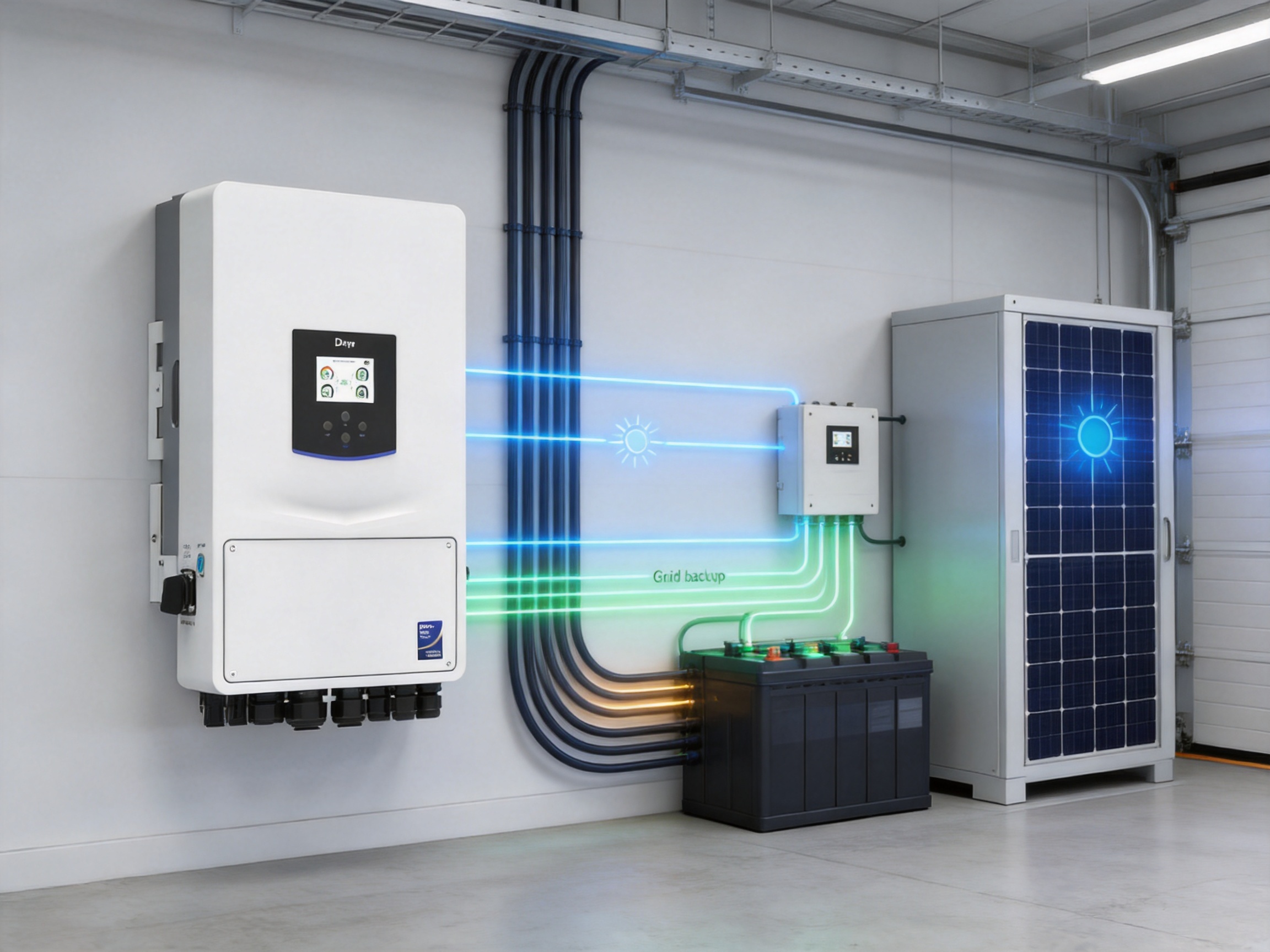
The inverter is designed for both on-grid and off-grid operation. In a grid-connected installation, it can manage solar generation, battery charging, local consumption, and grid import or export. In an off-grid or backup installation, it can form a stable local AC supply for designated loads when the utility is unavailable.
The system supports a peak off-grid power rating of two times the rated power for 10 seconds. Short-duration overload capability is important for starting motors, pumps, compressors, refrigerators, workshop equipment, and other loads that draw a high inrush current. The actual starting performance depends on the load characteristics, battery capability, wiring, ambient temperature, and the number of inverters operating in parallel.
Grid-to-load continuous passthrough capability is rated at up to 65 A or 70 A, depending on the specified model grouping. This allows a significant load current to pass from the grid to connected loads when the grid is available. It can be valuable in systems where the inverter must support high demand without forcing all power through the battery conversion stage.
The inverter supports a maximum of 16 units in parallel for on-grid and off-grid operation. Parallel operation can increase total power, improve system flexibility, and support larger single-phase loads than one unit could handle alone. It may also provide a path for staged expansion: an owner can begin with one inverter and add additional units when demand or budget allows, subject to the system’s design rules.
Parallel systems require careful engineering. Units must be configured according to the installation manual, phase and neutral arrangements must be correct, communication wiring must be properly terminated, and all connected batteries must be capable of sharing current. Protection devices, cable sizes, disconnects, grounding, and load distribution must be selected for the combined system rather than for one inverter only.
Support for multiple batteries in parallel complements the multi-inverter architecture. Additional battery capacity can extend backup duration and reduce battery depth of discharge during daily operation. As with all parallel battery systems, modules should be compatible, properly balanced, protected, and installed according to the battery supplier’s requirements.
Energy Scheduling and Generator Integration
The inverter provides six time periods for battery charging and discharging. Time-of-use energy management is increasingly important in markets with variable electricity tariffs. Users can schedule the battery to charge during periods of low-cost grid electricity, discharge during expensive periods, or reserve capacity for anticipated outages.
Scheduling can also improve solar self-consumption. The battery may be charged from solar during the day and discharged in the evening when household or business demand rises. If the system exports power to the grid, time periods can help coordinate export behavior with local tariff structures and grid requirements.
Six programmable periods offer more flexibility than a simple day-and-night schedule. A system can be configured around morning demand, daytime solar production, afternoon tariff changes, evening consumption, overnight standby, and a separate reserve strategy. The exact operating logic depends on firmware settings, local requirements, battery limits, and the user’s energy objectives.
The inverter can store energy from a diesel generator. This feature extends its usefulness beyond conventional solar-plus-battery applications. In remote sites, agricultural operations, construction locations, workshops, and areas affected by unreliable grid supply, a generator may be needed for extended periods of poor weather or heavy demand.
Generator integration allows generated electricity to serve loads and charge the battery through the inverter’s energy management system. This can reduce generator operating time, prevent unnecessary low-load operation, and provide a more controlled transition between energy sources. Generator compatibility must be verified against the generator’s voltage, frequency, neutral configuration, waveform, grounding arrangement, and control requirements.
AC Coupling for Solar Retrofit Projects
AC coupling is one of the most practical features for existing solar owners. Many early photovoltaic systems were installed with grid-tie inverters that did not include battery charging or backup capability. Replacing those inverters may be expensive and waste useful equipment. An AC-coupled hybrid system can add storage while preserving much of the original solar infrastructure.
In an AC-coupled arrangement, the existing solar inverter produces AC power, while the hybrid inverter monitors the site’s power flow and controls battery charging or discharging. Surplus AC energy can be directed into the battery, and stored energy can later support local loads. During a grid outage, the hybrid inverter can establish a local grid for compatible equipment, although the detailed behavior of the existing solar inverter must be checked carefully.
Retrofit projects require close attention to compatibility. The installer must verify the existing inverter’s power rating, anti-islanding behavior, frequency response, backup configuration, and communication or control method. The final system should comply with local grid rules and the manufacturer’s installation instructions. When properly planned, AC coupling can shorten project duration and make energy storage accessible to properties that already have operational solar equipment.
This retrofit capability gives the product an advantage over battery inverters that are limited to DC-coupled solar systems. It also allows owners to phase their investment: solar may be installed first, followed by storage and backup when energy needs change.
Electrical Performance
The rated AC active output ranges from 7,000 W to 12,000 W. Maximum AC input and output apparent power ranges from 7,700 VA to 13,200 VA. Rated AC input and output current varies by model, with the 12 kW version specified at 54.6 A input and 52.2 A output. Maximum AC input and output current for the 12 kW version is 60 A and 57.4 A.
The inverter is designed for single-phase 220/230 V systems with line, neutral, and protective earth connections. The specified operating voltage range is 0.85 to 1.1 times the nominal voltage. Grid frequency settings support 50 Hz with a 45–55 Hz range and 60 Hz with a 55–65 Hz range.
Power factor adjustment extends from 0.8 leading to 0.8 lagging. This provides reactive power management capability where permitted by the grid operator and local regulations. Such control can help meet utility requirements and support voltage management in certain installations.
Total current harmonic distortion is specified at less than 3 percent at nominal power. Low harmonic distortion helps reduce the effect of inverter operation on connected electrical equipment and supports compliance with relevant power quality expectations. DC injection current is specified at less than 0.5 percent of nominal current.
Maximum efficiency is rated at 97.6 percent, Euro efficiency at 96.5 percent, and MPPT efficiency above 99 percent. Maximum efficiency is a peak value, while Euro efficiency is intended to reflect a weighted operating profile. Actual site performance will depend on battery state of charge, temperature, operating mode, load level, cable losses, solar conditions, and grid behavior.
Protection and Operational Safety
Protection functions are integrated into the inverter to reduce the need for separate internal protection components and to improve the coordination of system monitoring. Listed functions include DC reverse polarity protection, AC output overcurrent protection, thermal protection, AC output overvoltage protection, AC output short-circuit protection, DC component monitoring, anti-islanding protection, a DC switch, insulation impedance detection, and residual current detection.
Arc fault circuit interruption is available as an option. Arc fault protection can be valuable in reducing the risk associated with certain abnormal DC conditions, but availability and regulatory requirements must be confirmed for the target market and final product configuration.
Type II surge protection is provided on both the DC and AC sides. Surge protection helps protect the inverter against transient overvoltage events, although a complete installation may still require additional external surge protective devices depending on the site, lightning risk, cable lengths, and local electrical code.
The inverter has an IP65 ingress protection rating. This indicates a high level of protection against dust ingress and water jets from multiple directions when the enclosure is correctly installed. IP65 does not mean the inverter can be submerged, installed in any outdoor location without shelter, or exposed to conditions outside the specified environmental limits.
The permissible ambient humidity range is 0–100 percent, and the permissible altitude is up to 3,000 meters. The operating temperature range is –40 to +60 degrees Celsius, with derating above 45 degrees Celsius. Proper ventilation and clearance remain essential, particularly in hot climates or enclosed plant rooms.
The inverter uses intelligent air cooling. The specified noise level is below 45 dB, supporting installation near homes, offices, and other areas where acoustic comfort matters. The cooling system should remain unobstructed, and dust accumulation should be addressed through routine inspection.
Durable Mechanical Design
The compact IP65 enclosure combines protection, serviceability, and installation flexibility. A wall-mounted form factor can help preserve floor space and reduce the need for a dedicated equipment cabinet. The relatively moderate weight also supports practical handling during installation, although suitable lifting and mounting procedures remain necessary.
The operating temperature range shows that the design is intended for demanding environments, from cold outdoor locations to hot climates. The derating point above 45 degrees Celsius is important for system planning. Installers should avoid direct exposure to intense solar heating where possible and provide the clearances required for cooling and maintenance.
The non-isolated solar topology and isolated battery topology reflect different functional requirements within the product. The battery side uses isolation to support safety and system separation, while the solar conversion stage uses a non-isolated architecture. The specified overvoltage categories are OVC II for DC and OVC IV for AC.
Mechanical durability is not determined by the enclosure rating alone. Long service life also depends on component quality, thermal management, printed circuit board protection, connector design, firmware stability, inspection procedures, and manufacturing consistency. These factors are part of the broader manufacturing strengths of the producer.
Manufacturing Strengths and Product Development Capability
Ningbo Deye Inverter Technology Co., Ltd. was founded in 2000 and operates as a technology manufacturing enterprise covering research and development, design, production, sales, and service. This integrated structure is important in a power electronics industry where product reliability depends on close coordination between electrical engineering, firmware, mechanical design, production control, testing, and field support.
The company has developed product lines covering photovoltaic string inverters, energy storage inverters, microinverters, residential energy storage, commercial and industrial storage, electric vehicle charging, and related energy management solutions. This breadth can support cross-platform engineering knowledge. For example, experience with grid-connected conversion, battery control, communications, and thermal management can contribute to the development of a more capable hybrid inverter.
Manufacturing scale is also relevant to product availability and support. A supplier with established production capability can coordinate component sourcing, assembly, quality inspection, firmware deployment, packaging, and global logistics through a more structured process. For distributors and installers, this may reduce uncertainty during project planning and replacement procurement.
Advanced manufacturing in inverter production involves several important stages. Electronic components must be screened and stored under controlled conditions. Printed circuit boards require accurate automated placement and soldering. High-current pathways must be designed and assembled to manage heat, electrical stress, and mechanical vibration. Power semiconductor devices must be integrated with appropriate thermal interfaces. Enclosures, connectors, fans, sensors, and control boards must be assembled according to defined procedures.
Testing is equally important. A professional inverter manufacturing process typically includes visual inspection, electrical continuity checks, insulation testing, grounding verification, firmware loading, functional testing, thermal assessment, and simulated operating checks. Units must be evaluated under different input and output conditions to verify that protection functions, communication interfaces, control algorithms, and display behavior operate as intended.
For a high-current low-voltage hybrid inverter, production control is particularly significant. Current levels up to 250 A place demands on busbars, terminals, relays, fuses, current sensors, cable interfaces, and thermal pathways. Manufacturing consistency helps ensure that each unit meets the intended electrical and mechanical specifications rather than relying only on design performance demonstrated by a prototype.
The company’s international presence also supports product development for different regulatory environments. The inverter lists grid regulations and standards including IEC 61727, IEC 62116, CEI 0-21, EN 50549, NRS 097, RD 140, UNE 217002, OVE-Richtlinie R25, G99, and VDE-AR-N 4105. The applicable standard depends on the installation country, grid connection type, firmware configuration, and certification documentation.
Safety and electromagnetic compatibility references include IEC/EN 61000-6-1, IEC/EN 61000-6-2, IEC/EN 61000-6-3, IEC/EN 61000-6-4, IEC/EN 62109-1, and IEC/EN 62109-2. These references demonstrate that the product is designed within recognized international frameworks for inverter safety and electromagnetic performance. Project documentation should always confirm the exact approvals required by the local authority or utility.
How the Product Compares with Common Alternatives
Compared with Basic Grid-Tie Inverters
A basic grid-tie inverter may offer efficient solar conversion but usually cannot provide battery backup, generator charging, or independent off-grid operation. The hybrid inverter adds these capabilities in a single platform. It can be a more suitable choice for users who value energy resilience, self-consumption, and future storage expansion.
Compared with Small Hybrid Inverters
Many residential hybrid inverters are designed for lower power levels and may have limited battery current. The 7–12 kW range and maximum battery current up to 250 A give this series greater capacity for high-demand homes, small businesses, pumps, workshops, and backup circuits. The two-times-rated-power overload capability can also help with short-duration motor starting.
Compared with High-Voltage Battery Systems
High-voltage batteries can reduce current on the battery cables, but they may have stricter compatibility requirements and a narrower selection in some markets. This series supports 40–60 V batteries, including lead-acid and lithium-ion options. The low-voltage design can be attractive to installers who prefer widely available battery platforms or who need to integrate with an existing low-voltage storage system.
Compared with Separate Inverter Components
A system assembled from a grid-tie inverter, battery inverter, transfer switch, generator controller, and separate monitoring equipment may provide flexibility, but it can also increase installation complexity. An integrated hybrid inverter consolidates key functions and may simplify system architecture. The final decision should consider the required redundancy, serviceability, local regulations, and the installer’s technical capability.
Compared with Single-MPPT or Dual-MPPT Designs
Three MPPTs provide more flexibility for arrays with different orientations, shading patterns, or string lengths. This does not automatically make every system more productive, but it can reduce design compromises on complex roofs and multi-plane installations. The benefit is greatest when the solar array cannot be arranged as one uniform field.
Typical Applications
Residential backup is one of the primary applications. A household can connect solar modules, a low-voltage battery bank, grid supply, and selected backup loads. During normal operation, solar power can reduce grid consumption and charge the battery. During an outage, the inverter can supply essential lighting, refrigeration, communications equipment, security systems, water pumps, and other approved loads.
Small commercial buildings can use the inverter to reduce demand during expensive tariff periods. Shops, offices, clinics, restaurants, and workshops may benefit from scheduled battery discharge, solar self-consumption, and backup capability. Multiple units can be considered when the load profile exceeds the capacity of a single inverter.
Agricultural sites often have mixed energy requirements, including pumps, ventilation systems, refrigeration, lighting, and control equipment. The inverter’s solar oversizing capability and generator support can help create a flexible energy system for locations with variable grid access or seasonal demand.
Remote and semi-off-grid facilities can combine photovoltaic modules, low-voltage batteries, and a diesel generator. Solar can cover daytime loads and charge the battery, while the generator can support extended periods of poor weather or unusually high consumption. The inverter’s control functions can help coordinate these sources without requiring the generator to run continuously.
Existing solar installations can be upgraded with AC-coupled storage. This approach is useful for property owners who want backup power or greater self-consumption without immediately replacing an operational grid-tie inverter. The final retrofit design must verify compatibility and ensure that the existing equipment behaves correctly during grid-forming operation.
Installation and System Design Considerations
The inverter should be installed by qualified personnel familiar with photovoltaic systems, battery storage, single-phase distribution, and local electrical regulations. Although the product includes multiple protection functions, external circuit protection, isolation, grounding, surge protection, and cable management must be designed for the complete installation.
Battery cables require special attention because low-voltage operation can involve very high current. Cable length should be minimized where practical, conductor cross-sectional area must be suitable, terminals must be correctly crimped and tightened, and battery fusing must be coordinated with the battery and inverter ratings. Loose or undersized connections can cause voltage drop, heat generation, nuisance protection trips, or equipment damage.
Photovoltaic string voltage must remain within the inverter’s operating and absolute maximum limits under all expected temperatures. The cold-weather open-circuit voltage of a string can be higher than its value under standard test conditions. The installer must also compare module short-circuit current and maximum operating current with the relevant MPPT input ratings.
AC protection should reflect the model’s rated and maximum current. Distribution boards, breakers, isolators, residual current protection, cable sizes, and grid connection equipment must comply with local regulations. Backup and non-backup loads should be separated clearly where required.
Communication interfaces include Wi-Fi, RS485, and CAN. Wi-Fi can support monitoring and configuration, while RS485 and CAN can connect batteries, meters, control devices, or parallel inverter systems. Communication wiring should be routed to reduce electromagnetic interference, and battery communication protocols must be confirmed before commissioning.
The colorful touch LCD provides local access to operating information and settings. A clear local interface is valuable during installation and maintenance because technicians can review alarms, power flow, battery status, grid conditions, and operating modes without relying exclusively on a remote application.
Monitoring and Energy Management
Monitoring is essential for maintaining a modern energy system. Users need visibility into photovoltaic production, battery charge and discharge, grid import and export, load consumption, generator operation, and alarms. The inverter’s communication interfaces provide a foundation for local and remote data access, depending on the selected monitoring equipment and system configuration.
Monitoring can reveal changes in performance before they become serious problems. A sudden decline in PV production may indicate shading, a string fault, connector damage, or a tripped protection device. Unexpected battery behavior may indicate a communication issue, temperature condition, state-of-charge limit, or aging battery module. Early information helps installers diagnose problems efficiently.
Time-period scheduling also turns monitoring data into practical energy management. Users can compare tariff costs with solar production and battery behavior, then adjust charging and discharging windows. A system designed for backup priority may maintain a high reserve state of charge, while a system designed for energy-cost reduction may cycle the battery more frequently.
Battery operation should always be balanced against battery life. Maximum charging and discharging current does not mean the battery should operate at that level continuously. The appropriate current depends on battery chemistry, capacity, temperature, manufacturer instructions, and the desired service life.
Reliability, Warranty, and Lifecycle Support
The product is listed with a five-year or ten-year warranty, depending on the final installation site and applicable warranty policy. Warranty duration is an important consideration, but buyers should also review the specific coverage conditions, registration requirements, service process, exclusions, labor provisions, and approved installation practices.
Reliable operation depends on correct system design and commissioning. The inverter should not be installed in a location that exceeds its environmental limits or blocks its cooling path. Battery and PV connections should be inspected periodically, and firmware or communication settings should be maintained according to the supplier’s guidance.
A manufacturer with dedicated research, production, sales, and service functions can provide advantages over a supplier that only rebrands products from an unrelated factory. Direct control of product development and manufacturing may improve the ability to investigate field issues, release firmware updates, coordinate spare parts, and adapt products to regulatory requirements.
Deye’s stated business covers more than 140 countries and regions, creating experience across diverse climates, grid conditions, installation practices, and market requirements. International experience does not eliminate the need for local technical support, but it can contribute to broader product validation and application knowledge.
Technical Summary
| Specification | Series Value or Range |
|---|---|
| Product category | Single-phase low-voltage hybrid inverter |
| Available rated power | 7 kW, 7.6 kW, 8 kW, 10 kW, and 12 kW |
| Battery type | Lead-acid or lithium-ion |
| Battery voltage range | 40–60 V |
| Maximum battery current | 175–250 A, depending on model |
| Maximum PV access power | 14–24 kW, depending on model |
| Maximum DC input voltage | 500 V |
| Start-up voltage | 125 V |
| MPPT voltage range | 150–425 V |
| Number of MPPTs | 3 |
| Maximum off-grid peak power | Two times rated power for 10 seconds |
| Parallel operation | Up to 16 units for on-grid and off-grid operation |
| Maximum efficiency | 97.6% |
| MPPT efficiency | Above 99% |
| Protection rating | IP65 |
| Communication | Wi-Fi, RS485, and CAN |
| Operating temperature | –40 to +60 degrees Celsius, with derating above 45 degrees Celsius |
| Maximum permissible altitude | 3,000 meters |
| Cooling | Intelligent air cooling |
Frequently Asked Questions
What type of inverter is this product?
It is a single-phase low-voltage hybrid inverter designed to manage solar PV generation, batteries, utility grid power, backup loads, and compatible generator sources. It can operate in grid-connected and off-grid applications.
What power ratings are available?
The series includes 7 kW, 7.6 kW, 8 kW, 10 kW, and 12 kW models. Selecting the correct model depends on continuous load power, motor starting requirements, battery capacity, PV array size, local grid limits, and future expansion plans.
What batteries can be used?
The inverter supports lead-acid and lithium-ion batteries with a 40–60 V battery voltage range. Lithium-ion systems should use a compatible battery management system and communication connection. Battery selection must follow the battery manufacturer’s specifications.
What is the maximum battery current?
Maximum charging and discharging current ranges from 175 A for the 7 kW model to 250 A for the 12 kW model. The precise value depends on the selected model. The battery, cables, fuses, terminals, and protection devices must all be rated for the actual current.
Can the inverter be added to an existing solar system?
Yes. The product supports AC coupling for solar retrofit applications. However, the existing solar inverter, grid protection behavior, power rating, backup configuration, and local regulations must be assessed before installation.
How many MPPTs does it have?
The inverter has three MPPTs. This can improve design flexibility when solar strings have different orientations, shading conditions, tilt angles, or string arrangements.
Can several inverters operate together?
Up to 16 units can operate in parallel for on-grid and off-grid operation, subject to the installation manual and system design requirements. Parallel battery configuration, communication, protection, and load distribution require careful commissioning.
Can it work with a diesel generator?
Yes. The product supports storing energy from a diesel generator. Generator voltage, frequency, grounding, neutral arrangement, power rating, and control compatibility must be checked before commissioning.
Does it provide backup power during a grid outage?
It is designed for off-grid and backup operation. The backup system must be configured correctly, and loads should be selected according to the inverter’s continuous output, short-term peak capability, battery power, and installation regulations.
What is its peak off-grid output?
The specified peak off-grid power is two times the rated power for 10 seconds. This short-duration capability can assist with starting certain motors and other equipment with high inrush current. It does not mean that the inverter can operate continuously at twice its rated output.
What protection functions are integrated?
Integrated functions include DC reverse polarity protection, AC overcurrent and overvoltage protection, thermal protection, AC short-circuit protection, anti-islanding protection, DC switching, insulation impedance detection, residual current detection, and DC component monitoring. Type II surge protection is listed for both DC and AC sides. Arc fault interruption is optional.
Is the inverter suitable for outdoor installation?
The IP65 enclosure rating and operating temperature range support many indoor and outdoor applications. The unit still needs correct mounting, ventilation, clearance, protection from unsuitable exposure, and compliance with the installation manual. IP65 does not permit immersion or installation in every unprotected environment.
How efficient is the inverter?
Maximum efficiency is rated at 97.6 percent, Euro efficiency at 96.5 percent, and MPPT efficiency above 99 percent. Actual efficiency varies with load, temperature, battery state, operating mode, and other system conditions.
What communication interfaces are available?
The inverter provides Wi-Fi, RS485, and CAN interfaces. These can support monitoring, battery communication, meters, control devices, and parallel system coordination when the connected equipment is compatible.
What warranty is offered?
The listed warranty is five years or ten years, with the applicable period depending on the final installation site and the warranty policy. Buyers should confirm the current terms before purchase and retain installation and commissioning records.
Conclusion
The SUN-7/7.6/8/10/12K-SG06LP1-EU-CM3 series is a flexible hybrid platform for users who need more than basic solar conversion. Its combination of 7–12 kW single-phase output, low-voltage battery support, high charging and discharging current, three MPPTs, AC coupling, generator integration, six charging and discharging periods, and parallel operation creates a broad range of application possibilities.
Its strongest competitive advantages are practical rather than purely numerical. The inverter can support high-power low-voltage storage, accommodate complex PV layouts, retrofit existing solar systems, provide backup and off-grid capability, and grow through parallel operation. These features can reduce design limitations for residential, agricultural, remote, and small commercial projects.
The product’s value is also connected to the manufacturer’s broader capabilities. Deye combines research and development, product design, manufacturing, global sales, and service across a wide energy technology portfolio. This integrated background supports the development of power conversion equipment that must combine electrical performance, battery control, grid compliance, thermal management, communications, and safety protection.
As with any high-power energy storage system, the final result depends on correct engineering. PV strings, batteries, generator connections, protection devices, communication settings, load priorities, and local grid requirements must be evaluated by qualified professionals. When properly designed and installed, this hybrid inverter family can provide a scalable foundation for solar self-consumption, energy cost management, and dependable backup power.
References
Deye. Product datasheet for the SUN-7/7.6/8/10/12K-SG06LP1-EU-CM3 single-phase hybrid inverter series.
Deye. Installation and operation manual for the SUN-7/7.6/8/10/12K-SG06LP1-EU-CM3 series.
IEC 62109-1. Safety of power converters for use in photovoltaic power systems: General requirements.
IEC 62109-2. Safety of power converters for use in photovoltaic power systems: Particular requirements for inverters.
IEC 61727. Photovoltaic systems: Utility interface characteristics.
IEC 62116. Utility-interconnected photovoltaic inverters: Test procedure of islanding prevention measures.
EN 50549. Requirements for generators connected in parallel with distribution networks.
IEC 61000 series. Electromagnetic compatibility requirements and testing methods.
Product: SUN-7/7.6/8/10/12K-SG06LP1-EU-CM3

PREV:Advanced Single-Phase Solar Inverter Technology for Reliable Grid-Tied Power
NEXT:Three-Phase String Inverter Technology for Efficient Commercial Solar Systems
Share
Product recommendations
news recommendations
-
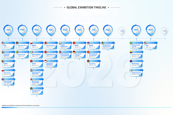 GLOBAL EXHIBITION TIMELINE
*Click to view larger image
-
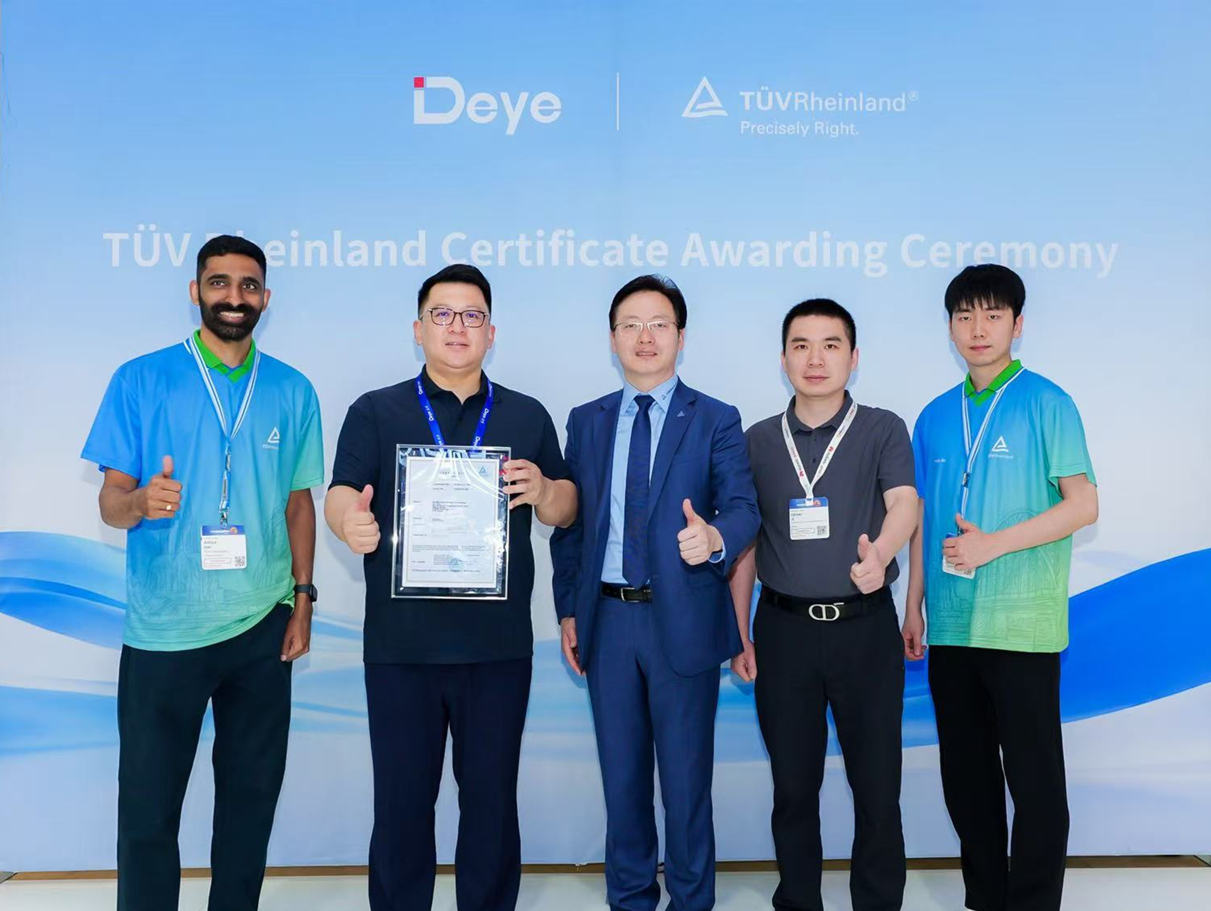 Deye Secures Multiple TÜV Rheinland Certifications at The smarter E Europe
On June 23, the opening day of The smarter E Europe 2026, Deye was officially awarded several presti...
-
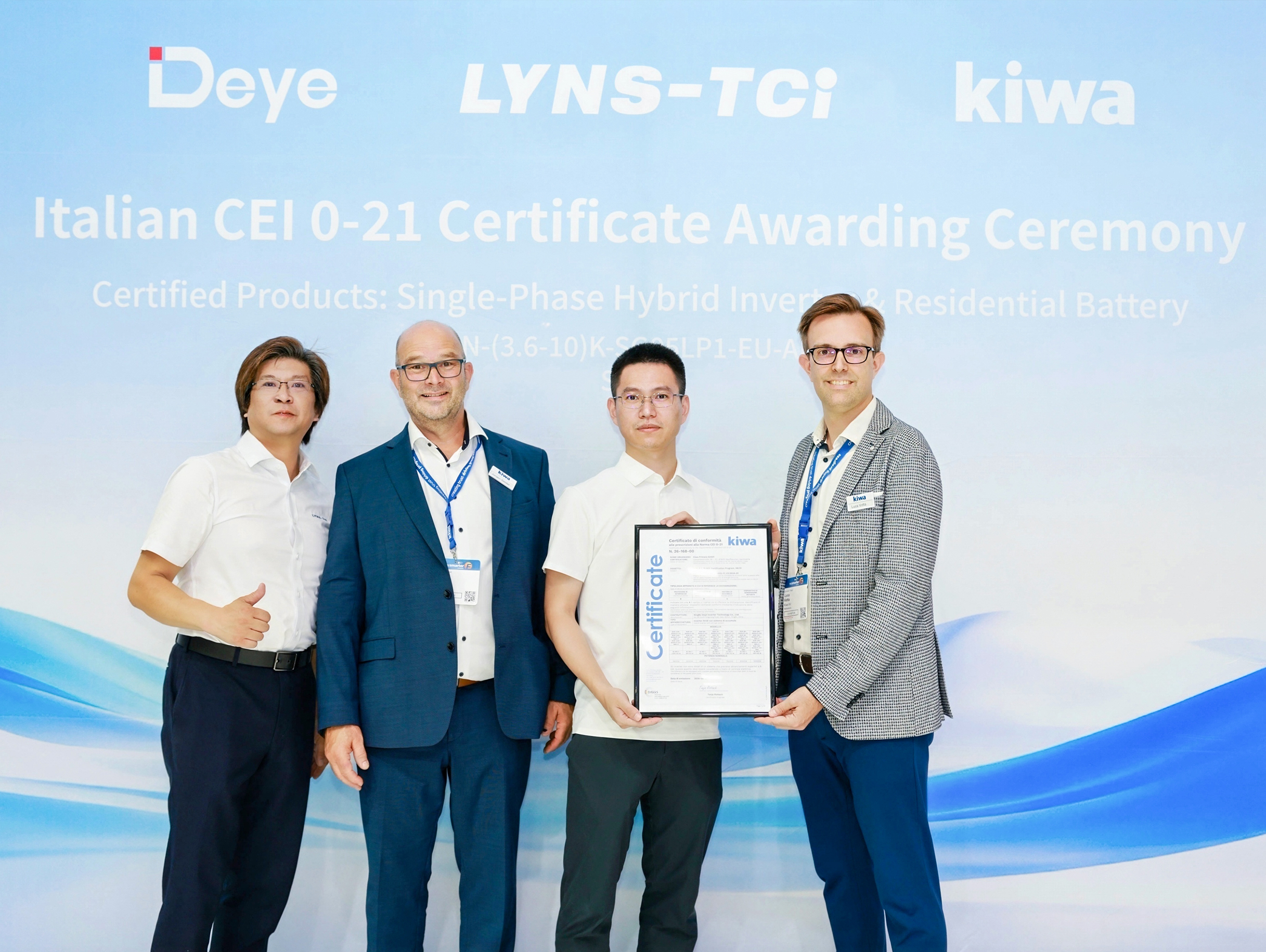 Deye Next-Gen Residential Energy Storage Products Receive Italian CEI 0-21 Certification from Kiwa
At The smarter E Europe 2026, Deye, a leading supplier of inverters and energy storage solutions, of...

Copyright@ 2024.Ningbo Deye Inverter Technology Co.,Ltd. All rights reserved. Solar Inverter Manufacturer
