 China - 简体中文
 Global - English
 Brazil - Português
 Netherlands - Dutch
 Italy - Italiano
 Germany - Deutsch
 Spain - Español
 France - Français
 Vietnam - Tiếng Việt
 Poland - Polski
 Australia - English
 Japan - 日本語
Technical Topics
Understand the working principle of photovoltaic inverters in one article
From the article to understand the working principle of photovoltaic inverters!
Working principle and characteristics Working principle: The core of the inverter device is the inverter switching circuit, referred to as the inverter circuit for short. This circuit completes the function of inverter by turning on and off the power electronic switch. Features: (1) High efficiency is required. Due to the high price of solar cells, in order to maximize the use of solar cells and improve system efficiency, we must try to improve the efficiency of the inverter. (2) High reliability is required. At present, photovoltaic power station systems are mainly used in remote areas. Many power stations are unattended and maintained. This requires inverters to have a reasonable circuit structure, strict component selection, and require inverters to have various protection functions, such as: input DC polarity reverse protection, AC output short circuit protection, overheating, overload protection, etc. (3) The input voltage is required to have a wide range of adaptation. Because the terminal voltage of the solar cell changes with the load and the intensity of sunlight. Especially when the battery is aging, its terminal voltage varies widely. For example, the terminal voltage of a 12V battery may vary from 10V to 16V, which requires the inverter to ensure normal operation within a larger DC input voltage range.
Photovoltaic inverter classification There are many methods for inverter classification, for example: according to the number of phases of the inverter output AC voltage, it can be divided into single-phase inverters and three-phase inverters; according to the semiconductor devices used in the inverter Different types can be divided into transistor inverters, thyristor inverters and turn-off thyristor inverters. According to the principle of the inverter circuit, it can be divided into self-excited oscillation inverter, stepped wave superposition inverter and pulse width modulation inverter. According to the application in grid-connected system or off-grid system, it can be divided into grid-connected inverter and off-grid inverter. In order to facilitate the selection of inverters for photovoltaic users, the classification is only based on the different applicable occasions of the inverters.
1. Centralized inverter Centralized inverter technology is that several parallel photovoltaic strings are connected to the DC input end of the same centralized inverter. Generally, three-phase IGBT power modules are used for high power, and the use of low power Field effect transistor, while using DSP conversion controller to improve the quality of the generated electric energy, making it very close to the sine wave current, generally used in the system of large photovoltaic power stations (>10kW). The biggest feature is the high power and low cost of the system. However, because the output voltage and current of different photovoltaic strings are often not completely matched (especially when the photovoltaic strings are partially shaded due to cloudy, shade, stains, etc.), centralized inversion is adopted. The method of change will guide to a decrease in the efficiency of the inverter process and a decrease in the energy of the electricity users. At the same time, the power generation reliability of the entire photovoltaic system is affected by the poor working status of a photovoltaic unit group. The latest research direction is the use of space vector modulation control and the development of new inverter topology connections to obtain high efficiency under partial load conditions.
2. String inverters String inverters are based on the modular concept. Each photovoltaic string (1-5kw) passes through an inverter and has max. power peak tracking at the DC end. Parallel and grid connection has become the more popular inverter in the international market. Many large photovoltaic power plants use string inverters. The advantage is that it is not affected by module differences and shadows between strings, and at the same time reduces the mismatch between the better working point of the photovoltaic module and the inverter, thereby increasing the power generation. These technical advantages not only reduce the cost of the system, but also increase the reliability of the system. At the same time, the concept of "master-slave" is introduced between the strings, which makes the system connect several PV strings together and let one or several of them work when a single string of electric energy cannot make a single inverter work. , So as to produce more electricity. The latest concept is that several inverters form a "team" to replace the "master-slave" concept, which makes the reliability of the system a step further. Currently, transformerless string inverters have taken the guide.
3. Micro-inverter In the traditional PV system, the DC input terminal of each string inverter will be connected in series by about 10 photovoltaic panels. When one of the 10 panels connected in series does not work well, this string will be affected. If the inverter uses the same MPPT for multiple inputs, each input will also be affected, greatly reducing the power generation efficiency. In practical applications, various sheltering factors such as clouds, trees, chimneys, animals, dust, ice and snow will cause the above factors, and the situation is very common. In the PV system of the micro-inverter, each panel is connected to a micro-inverter. When one of the panels does not work well, only this one will be affected. All other photovoltaic panels will run in the better working condition, making the overall system more efficient and generating more power. In practical applications, if the string inverter fails, it will cause the panels of several kilowatts to fail to function, and the impact of the failure of the micro-inverter is quite small.
4. Power optimizer The installation of a power optimizer (OptimizEr) in the solar power generation system can greatly improve the conversion efficiency and simplify the inverter (Inverter) function to reduce costs. In order to realize a smart solar power generation system, the device power optimizer can ensure that each solar cell exerts the better performance and monitor the battery consumption status at any time. The power optimizer is a device between the power generation system and the inverter. The main task is to replace the original better power point tracking function of the inverter. The power optimizer uses analogy to perform greatly fast better power point tracking scans by simplifying the circuit and a single solar cell corresponds to a power optimizer, so that each solar cell can indeed achieve the better power point tracking In addition, you can also monitor the battery status anytime and anywhere by inserting a communication chip, report problems in real time, and allow relevant personnel to repair them as soon as possible. The function of the photovoltaic inverter The inverter not only has the function of direct-to-ac conversion, but also has the function of max. the performance of the solar cell and the function of system failure protection. In summary, there are automatic operation and shutdown functions, max. power tracking control function, anti-single operation function (for grid-connected system), automatic voltage adjustment function (for grid-connected system), DC detection function (for grid-connected system), DC grounding detection Function (for grid-connected system). Here is a brief introduction to the automatic operation and shutdown functions and the max. power tracking control function.
(1) Automatic operation and shutdown function After sunrise in the morning, the solar radiation intensity gradually increases, and the output of the solar battery also increases. When the output power required by the inverter is reached, the inverter automatically starts to operate. After entering operation, the inverter will monitor the output of the solar cell components at all times. As long as the output power of the solar cell components is greater than the output power required by the inverter, the inverter will continue to run; it will stop until sunset, even if it is cloudy or rainy. The inverter can also be operated. When the output of the solar cell module becomes smaller and the output of the inverter approaches 0, the inverter enters a standby state.
(2) Maximum power tracking control function The output of the solar cell module varies with the intensity of solar radiation and the temperature of the solar cell module itself (chip temperature). In addition, because the solar cell module has the characteristic that the voltage decreases with the increase of the current, there is an better operating point that can obtain the max. power. The intensity of solar radiation is changing, and obviously the better operating point is also changing. Relative to these changes, the operating point of the solar cell module is always at the max. power point, and the system always obtains the max. power output from the solar cell module. This kind of control is the max. power tracking control. The biggest feature of the inverter used in the solar power generation system is that it includes the function of Maximum Power Point Tracking (MPPT).
The main technical indicators of photovoltaic inverters
1. The stability of the output voltage In a photovoltaic system, the electric energy generated by the solar cell is 1st stored by the battery, and then converted into 220V or 380V alternating current through the inverter. However, the battery is affected by its own charging and discharging, and its output voltage varies widely. For example, the nominal 12V battery can vary from 10.8 to 14.4V (exceeding this range may cause damage to the battery). For a qualified inverter, when the input terminal voltage changes within this range, the change in its steady-state output voltage should not exceed Plusmn; 5% of the rated value. At the same time, when the load changes suddenly, its output voltage deviation should not It exceeds ± 10% of the rated value.
2. Waveform distortion of the output voltage For sine wave inverters, the max. allowable waveform distortion (or harmonic content) should be specified. Usually expressed by the total waveform distortion of the output voltage, its value should not exceed 5% (single-phase output allows l0%). Because the high-order harmonic current output by the inverter will produce additional losses such as eddy currents on the inductive load, if the inverter waveform distortion is too large, it will cause serious heating of the load components, which is not conducive to the safety of electrical equipment and seriously affects the system Operating efficiency. 3. Rated output frequency For loads that include motors, such as washing machines, refrigerators, etc., because the motor's better frequency operating point is 50Hz, too high or too low a frequency will cause the equipment to heat up, reducing the operating efficiency and service life of the system. Therefore, the output frequency of the inverter should be a relatively stable value, usually 50Hz, and its deviation should be within Plusmn;l% under normal working conditions.
4. The load power factor represents the ability of the inverter to carry inductive or capacitive loads. The load power factor of the sine wave inverter is 0.7 to 0.9, and the rated value is 0.9. In the case of a certain load power, if the power factor of the inverter is low, the capacity of the inverter required will increase. On the one hand, the cost will increase, and the apparent power of the AC circuit of the photovoltaic system will increase. As the current increases, losses will inevitably increase, and system efficiency will also decrease.
5. Inverter efficiency The efficiency of an inverter refers to the ratio of its output power to its input power under specified working conditions, expressed as a percentage. In general, the nominal efficiency of a photovoltaic inverter refers to a purely resistive load. , Efficiency at 80% load. As the overall cost of the photovoltaic system is relatively high, the efficiency of the photovoltaic inverter should be maximized, the system cost should be reduced, and the cost performance of the photovoltaic system should be improved. At present, the nominal efficiency of mainstream inverters is between 80% and 95%, and the efficiency of low-power inverters is required to be no less than 85%. In the actual design process of the photovoltaic system, not only the high-efficiency inverter should be selected, but also the reasonable configuration of the system should be adopted to make the photovoltaic system load work near the better efficiency point as much as possible.
6. Rated output current (or rated output capacity)
Indicates the rated output current of the inverter within the specified load power factor range. Some inverter products give the rated output capacity, and the unit is expressed in VA or kVA. The rated capacity of the inverter is when the output power factor is 1 (ie pure resistive load), the rated output voltage is the product of the rated output current. 7. Protection measures An inverter with excellent performance should also have complete protection functions or measures to deal with various abnormal situations during actual use, so as to protect the inverter itself and other components of the system from damage. (1) Input undervoltage protector: When the input voltage is lower than 85% of the rated voltage, the inverter should be protected and displayed. (2) Input overvoltage protector: When the input voltage is higher than 130% of the rated voltage, the inverter should be protected and displayed. (3) Overcurrent protection: The overcurrent protection of the inverter should be able to ensure timely action when the load is short-circuited or the current exceeds the allowable value to protect it from surge current damage. When the working current exceeds 150% of the rated, the inverter should be able to automatically protect. (4) The action time of the inverter short-circuit protection of the output short-circuit protector should not exceed 0.5s. (5) Input reverse connection protection: When the positive and negative input terminals are connected reversely, the inverter should have a protection function and display. (6) Lightning protection: The inverter should have lightning protection.
(7) Over-temperature protection, etc. In addition, for inverters without voltage stabilization measures, the inverter should also have output over-voltage protection measures to protect the load from over-voltage damage. 8. The starting characteristics represent the ability of the inverter to start with load and its performance during dynamic operation. The inverter should be guaranteed to start reliably under rated load. 9. Noise: Transformers, filter inductors, electromagnetic switches, fans and other components in power electronic equipment will generate noise. When the inverter is in normal operation, its noise should not exceed 80dB, and the noise of a small inverter should not exceed 65dB. Selection skills The selection of inverters must 1st consider having sufficient rated capacity to meet the requirements of the equipment for electrical power under the max. load. For an inverter with a single device as a load, the selection of its rated capacity is relatively simple. When the electrical equipment is a pure resistive load or the power factor is greater than 0.9, the rated capacity of the inverter is selected to be 1.1 to 1.15 times the capacity of the electrical equipment. At the same time, the inverter should also have the ability to resist the impact of capacitive and inductive loads. For general inductive loads, such as motors, refrigerators, air conditioners, washing machines, high-power water pumps, etc., when starting, the instantaneous power may be 5-6 times its rated power. At this time, the inverter will endure a large instantaneous power. surge. For such systems, the rated capacity of the inverter should have sufficient margin to ensure that the load can be started reliably, and the high-performance inverter can be started at full load for many times without damaging the power devices. For its own safety, small inverters sometimes need to use soft start or current limiting start. Installation precautions and maintenance
1. Before installation, check whether the inverter is damaged during transportation.
2. When choosing the installation site, it should be ensured that there is no interference from any other power electronic equipment in the surrounding area.
3. Before making electrical connections, be sure to use opaque materials to cover the photovoltaic panels or disconnect the DC side circuit breaker. Exposure to sunlight, photovoltaic arrays will generate dangerous voltages.
4. All installation operations must be completed by professional and technical personnel only.
5. The cables used in the photovoltaic system power generation system must be firmly connected, well insulated and of appropriate specifications. Development trend For solar inverters, improving the conversion efficiency of power is an eternal topic, but when the efficiency of the system is getting higher and higher, almore approaching 100%, further efficiency improvements will be accompanied by lower cost performance. Therefore, How to maintain a high efficiency and maintain a good price competitiveness will be an important topic at present. Compared with efforts to improve the efficiency of inverters, how to improve the efficiency of the entire inverter system is gradually becoming another important issue for solar energy systems. In a solar array, when a partial shadow of 2~3% of the area appears, for an inverter with an MPPT function, when the output power of the system is bad, there will even be a power drop of about 20%! To better adapt to situations like this, it is very effective to use one-to-one MPPT or multiple MPPT control functions for single or partial solar modules. Because the inverter system is in the state of grid-connected operation, the leakage of the system to the ground will cause serious safety problems; in addition, in order to improve the efficiency of the system, more of the solar arrays are connected in series to form a high DC output voltage; Due to the occurrence of abnormal conditions between the electrodes, it is easy to produce a DC arc. Due to the high DC voltage, it is very difficult to extinguish the arc and it is greatly easy to cause a fire. With the widespread adoption of solar inverter systems, system safety issues will also be an important part of inverter technology. In addition, the power system is ushering in smart。
The rapid development and popularization of power grid technology. A large number of solar and other new energy power systems are connected to the grid, which poses new technical challenges to the stability of the smart grid system. Designing an inverter system that can be more quickly, accurately, and intelligently compatible with smart grids will become a necessary condition for solar inverter systems in the future.
Generally speaking, the development of inverter technology is developed with the development of power electronics technology, microelectronic technology and modern control theory. With the passage of time, inverter technology is developing in the direction of higher frequency, higher power, higher efficiency, and smaller volume.
PREV:Requirements of PV inverter for working environment
NEXT:What are the main considerations for the selection of industrial and commercial photovoltaic inverters?
Share
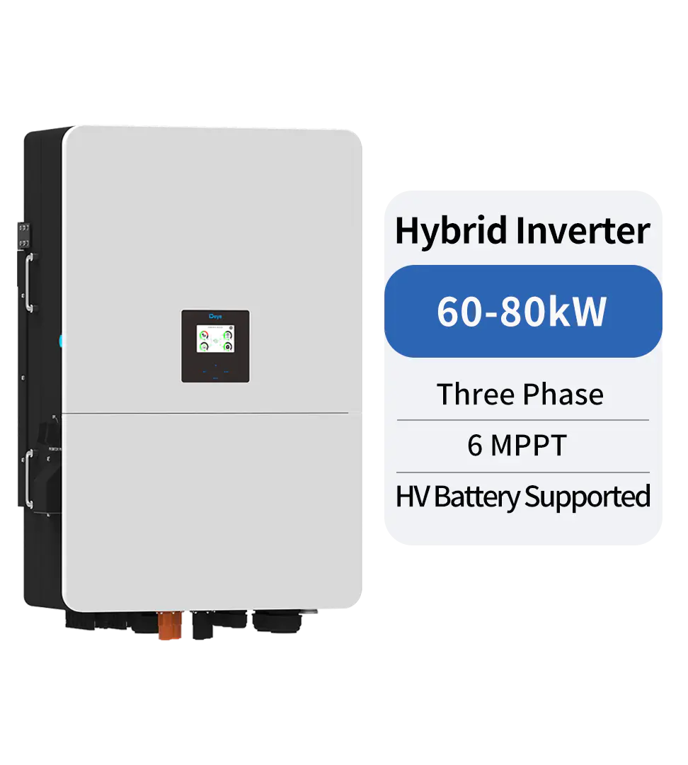
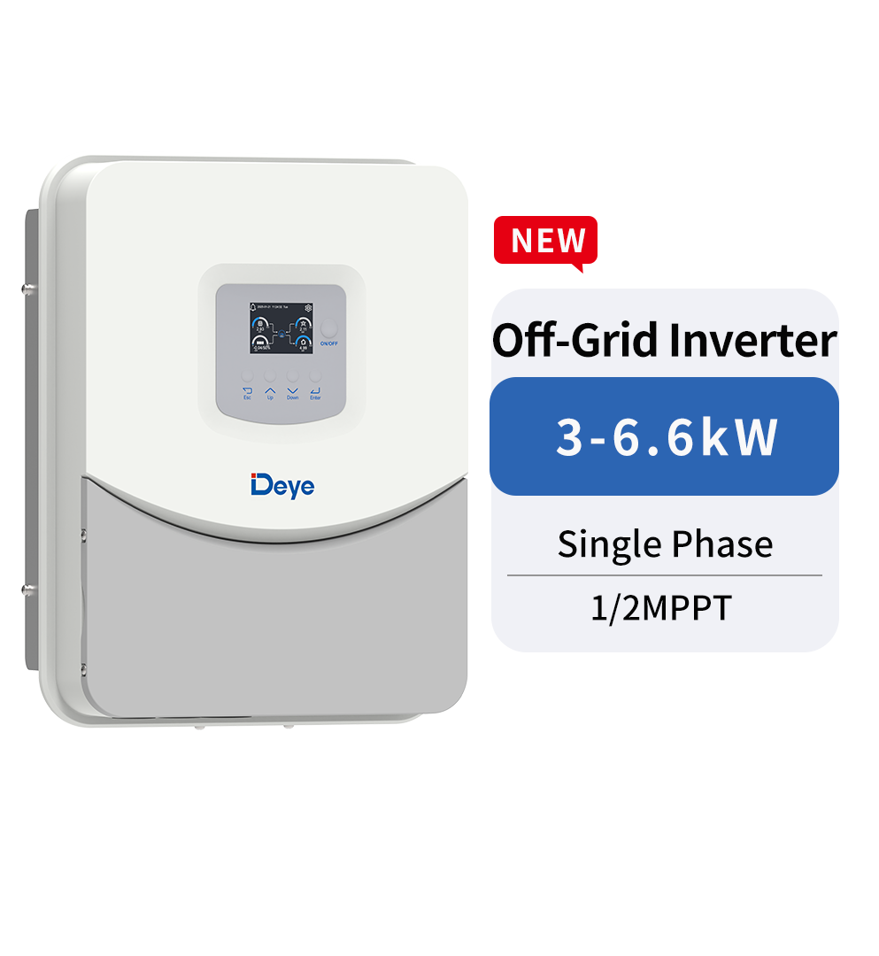
Product recommendations
news recommendations
-
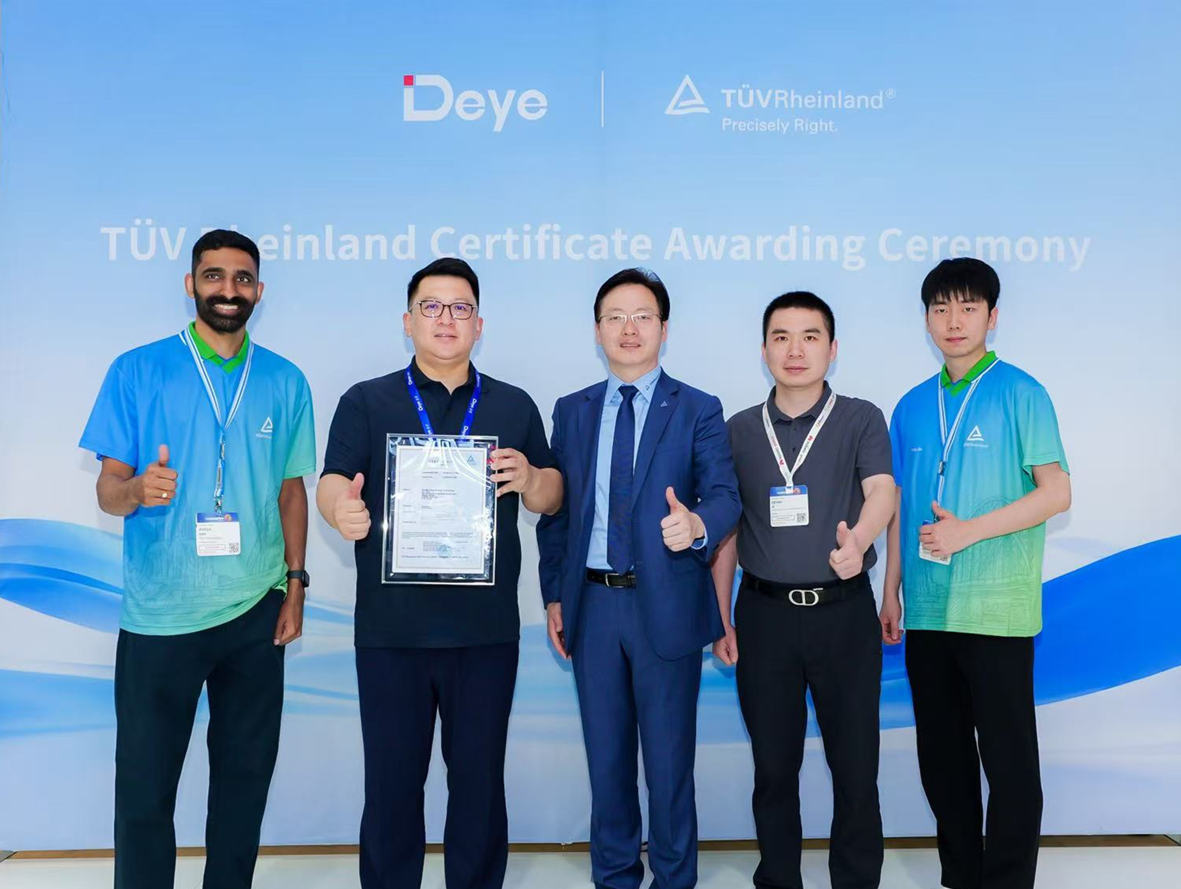 Deye Secures Multiple TÜV Rheinland Certifications at The smarter E Europe
On June 23, the opening day of The smarter E Europe 2026, Deye was officially awarded several presti...
-
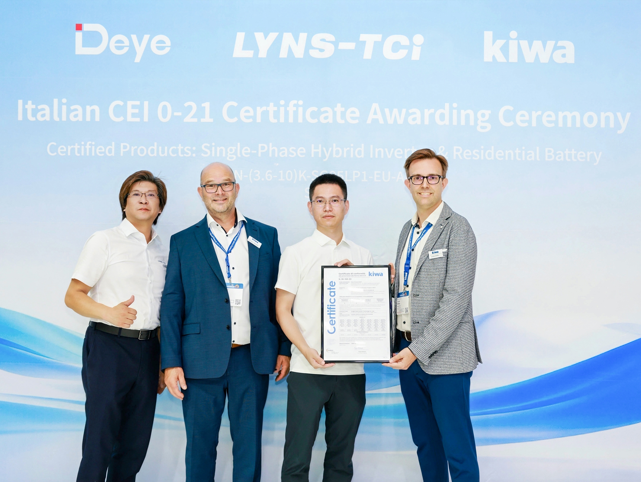 Deye Next-Gen Residential Energy Storage Products Receive Italian CEI 0-21 Certification from Kiwa
At The smarter E Europe 2026, Deye, a leading supplier of inverters and energy storage solutions, of...
-
 Deye Unveils Innovative Full-Scenario PV and Energy Storage Solutions at The smarter E Europe 2026
On June 23, The smarter E Europe, the world’s leading alliance of exhibitions for the energy industr...
Copyright@ 2024.Ningbo Deye Inverter Technology Co.,Ltd. All rights reserved. Solar Inverter Manufacturer
![]()