
 Online Shop
 English
 China - 简体中文
 Global - English
 Brazil - Português
 Netherlands - Dutch
 Italy - Italiano
 Germany - Deutsch
 Spain - Español
 France - Français
 Vietnam - Tiếng Việt
 Poland - Polski
 Australia - English
 Japan - 日本語
Luo Qinxue — Regional Sales Manager, On-Grid Inverter Solutions

Advanced Single-Phase Energy Independence with Flexible Low-Voltage Hybrid Inverter Technology
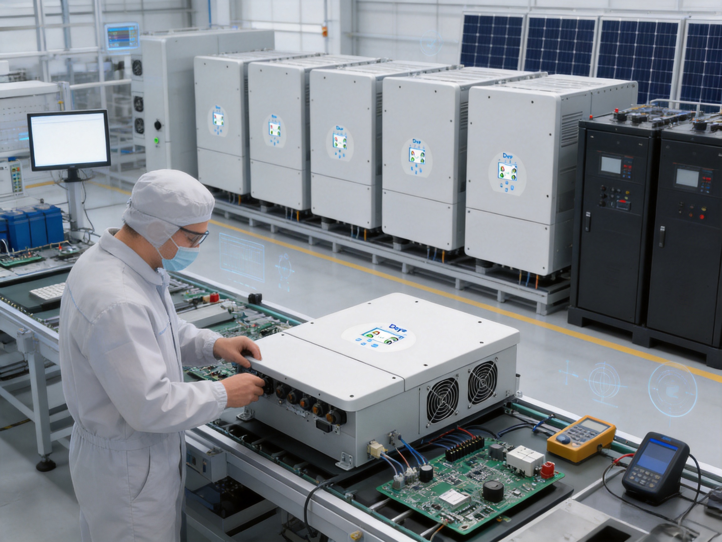
The transition toward cleaner, more resilient electricity is changing the way homes, small businesses, and distributed energy projects are designed. Solar generation is no longer limited to daytime self-consumption. With the right hybrid inverter, photovoltaic power can be stored, managed, and delivered when it is most valuable, while the electrical system can continue operating during grid interruptions.
The SUN-7.6/8/10/12K-SG02LP1-EU-AM2/AM3 product family is designed for this purpose. It is a single-phase low-voltage hybrid inverter platform with four power classes: 7.6 kW, 8 kW, 10 kW, and 12 kW. The range combines photovoltaic conversion, battery charging and discharging, grid interaction, backup power, generator integration, and advanced energy management in one system.
Its design is particularly relevant for installations that require substantial single-phase power while continuing to use low-voltage batteries. The inverter supports lead-acid or lithium-ion batteries, provides high battery current, accepts large photovoltaic arrays, and can be used in both on-grid and off-grid configurations. It can also be integrated with existing solar installations through AC coupling, giving users a practical route to expand or modernize an operating system.
Beyond its electrical specifications, the platform reflects a manufacturing approach based on product standardization, integrated protection, digital control, rigorous testing, and scalable production. These characteristics are important when comparing a hybrid inverter not only by its rated output, but also by its installation flexibility, operating durability, serviceability, and long-term suitability for changing energy requirements.
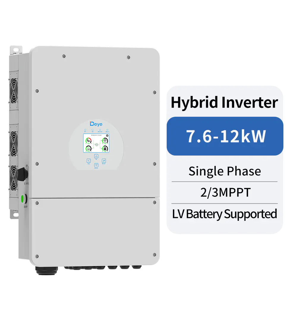
SUN-7.6/8/10/12K-SG02LP1-EU-AM2/AM3
Product Overview and Application Positioning
The SUN-7.6/8/10/12K-SG02LP1-EU-AM2/AM3 is a single-phase hybrid inverter for low-voltage battery systems. The product family covers rated AC active power from 7,600 W to 12,000 W, allowing system designers to choose a capacity that matches the building load, photovoltaic array, and expected battery behavior.
In contrast with a standard grid-tie inverter, this product is designed to coordinate multiple energy sources and operating modes. Solar energy can supply loads directly, charge the battery, or be exported to the grid. Stored battery energy can support loads during high-price periods, nighttime operation, or grid outages. Grid power can be used when solar and battery energy are insufficient, while a diesel generator can contribute energy to the system when required.
The inverter is suitable for several installation scenarios:
Residential properties with high single-phase loads can use the inverter to increase solar self-consumption and provide backup power.
Small commercial premises can combine photovoltaic generation with battery storage to reduce peak demand and improve energy availability.
Existing solar installations can be upgraded through AC coupling without necessarily replacing the original photovoltaic inverter.
Remote or weak-grid locations can use the inverter in off-grid or generator-supported applications.
Multi-inverter systems can be created by paralleling units, supporting larger energy storage and higher system capacity than a single inverter can provide.
This broad application range is one of the product family’s principal advantages. Instead of being limited to one fixed operating concept, the inverter can form part of a new solar-plus-storage installation or become the energy management core of an existing system.
Four Power Classes on One Platform
The product family is available in four models: SUN-7.6K-SG02LP1-EU-AM2, SUN-8K-SG02LP1-EU-AM2, SUN-10K-SG02LP1-EU-AM3, and SUN-12K-SG02LP1-EU-AM3. The common platform simplifies product selection, engineering, training, and maintenance.
The 7.6 kW and 8 kW models are suitable where the building demand is substantial but the system remains within a lower power range. The 10 kW and 12 kW models provide additional AC output capability and support larger photovoltaic arrays. The AM3 versions also provide three MPPT trackers, which can be beneficial where the roof or ground-mounted array contains several orientations, inclinations, or partial shading conditions.
| Model | Rated AC Active Power | Maximum PV Access Power | Maximum PV Input Power | Maximum Battery Current | MPPT Configuration |
|---|---|---|---|---|---|
| SUN-7.6K-SG02LP1-EU-AM2 | 7,600 W | 15,200 W | 12,160 W | 190 A | 2 MPPT, 2+2 strings |
| SUN-8K-SG02LP1-EU-AM2 | 8,000 W | 16,000 W | 12,800 W | 190 A | 2 MPPT, 2+2 strings |
| SUN-10K-SG02LP1-EU-AM3 | 10,000 W | 20,000 W | 16,000 W | 220 A | 3 MPPT, 2+2+2 strings |
| SUN-12K-SG02LP1-EU-AM3 | 12,000 W | 24,000 W | 19,200 W | 250 A | 3 MPPT, 2+2+2 strings |
The consistent enclosure dimensions, communication interfaces, protection architecture, and operating philosophy across the range help reduce design complexity. Installers can apply similar procedures to multiple power classes while selecting the output rating that best matches each project.
Low-Voltage Battery Compatibility and High-Current Operation
A major feature of this platform is its compatibility with low-voltage batteries operating from 40 V to 60 V. Low-voltage energy storage remains attractive in residential and small commercial applications because batteries are widely available, system architecture is familiar to installers, and battery modules can often be configured flexibly.
The inverter supports both lead-acid and lithium-ion battery technologies. Lithium-ion batteries can use a self-adaptive charging strategy through communication with the battery management system. This allows the inverter to respond to battery operating conditions and coordinate charging behavior with the battery’s protection and monitoring functions.
High current capability is essential when a low-voltage battery supplies a high-power inverter. At the same power level, a lower battery voltage requires higher current than a high-voltage battery system. The product range addresses this requirement with maximum charging and discharging currents of 190 A for the 7.6 kW and 8 kW models, 220 A for the 10 kW model, and 250 A for the 12 kW model.
The 12 kW version’s 250 A maximum charging and discharging current is especially significant for low-voltage energy storage. It enables the inverter to draw or deliver substantial battery power while remaining within the intended low-voltage architecture. Correct battery sizing, cable selection, fusing, disconnect equipment, ventilation, and installation practices remain essential, but the inverter’s current rating gives system designers a broad operating envelope.
The platform also supports multiple batteries in parallel. This can increase usable storage capacity and help distribute current among battery modules. Parallel battery configurations must be designed according to the battery manufacturer’s instructions, including requirements for communication, balancing, protection, cable length, and current sharing.
Six Time Periods for Energy Scheduling
The inverter provides six configurable time periods for battery charging and discharging. This function allows the system to follow a planned daily energy strategy rather than simply charging whenever solar energy is available.
For example, a system can charge from solar during the middle of the day, discharge during an evening demand period, reserve energy for a potential outage, and charge from the grid during a lower-cost tariff period. The exact strategy depends on electricity prices, local regulations, battery limitations, solar availability, and the user’s priorities.
Time-based operation can improve self-consumption and reduce unnecessary grid purchases. It can also support peak-load management by using stored energy when building demand rises. In regions with time-of-use tariffs, this feature may provide an important economic advantage over a basic inverter with limited scheduling functions.
Large Photovoltaic Input and Multi-MPPT Design
The photovoltaic input section is designed to accommodate large solar arrays. Maximum PV access power ranges from 15.2 kW on the 7.6 kW model to 24 kW on the 12 kW model. Maximum PV input power ranges from 12.16 kW to 19.2 kW, depending on the model.
This distinction allows designers to consider the difference between the connected array size and the maximum power processed by the inverter under operating conditions. Oversizing the array can help maintain useful generation during mornings, afternoons, low-irradiance periods, and seasons with reduced solar availability. The correct ratio must always be selected according to the applicable technical documentation, local standards, and project conditions.
All models have a maximum PV input voltage of 500 V, a start-up voltage of 125 V, an MPPT voltage range of 150 V to 425 V, and a rated PV input voltage of 370 V. These values give installers a defined electrical window for string design.
The 7.6 kW and 8 kW models use two MPPT trackers, with two strings allocated to each tracker. The 10 kW and 12 kW models use three MPPT trackers, with two strings allocated to each tracker. Independent MPPT tracking is valuable when solar modules are installed on multiple roof surfaces or when different array sections experience different shading and orientation conditions.
Maximum operating PV input current is 26 A plus 26 A for the two-MPPT versions and 26 A plus 26 A plus 26 A for the three-MPPT versions. Maximum input short-circuit current is 44 A plus 44 A for the two-MPPT versions and 44 A plus 44 A plus 44 A for the three-MPPT versions. These current ratings should be checked against the electrical characteristics of the selected PV modules and string configuration.
Advantages of Multi-MPPT Architecture
Compared with a single-tracker design, a multi-MPPT platform can reduce the electrical impact of mismatched array conditions. A roof facing east may produce a different voltage and current profile from a roof facing south. Similarly, a section affected by a chimney, tree, parapet, or neighboring building may not operate at the same maximum power point as an unobstructed section.
By separating suitable strings across independent trackers, the inverter can seek the best operating point for each group. This does not eliminate the effects of shading, but it can improve the ability of the system to capture available energy across complex array layouts.
The three-MPPT configuration of the 10 kW and 12 kW models is therefore an advantage for larger installations with more varied roof geometries. It can simplify string planning and may reduce the need for external optimization equipment in some applications, although project-specific shading analysis is still necessary.
AC Coupling and System Modernization
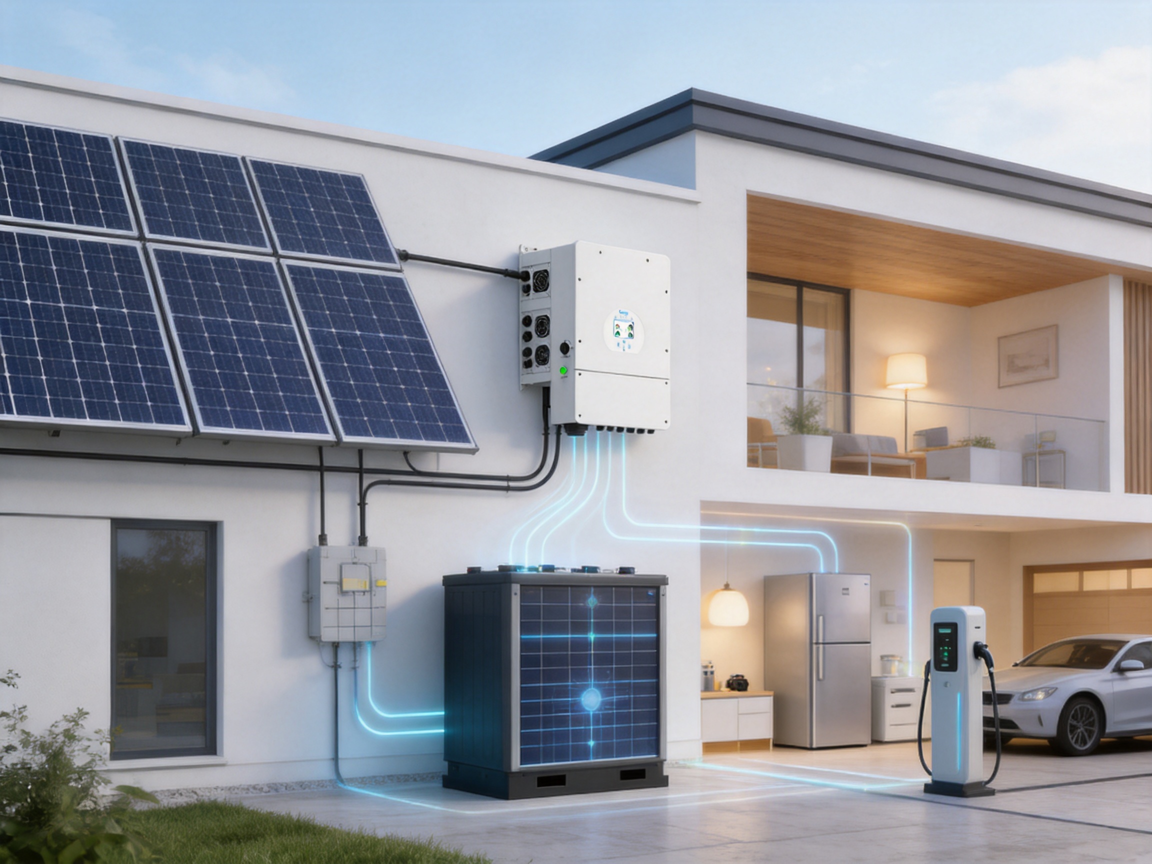
One of the product family’s practical strengths is AC coupling for retrofitting an existing solar system. In a conventional solar installation, an existing grid-tie inverter may already be operating correctly, while the owner later decides to add batteries and backup capability. Replacing the original inverter can create additional cost, downtime, and design work.
With an AC-coupled architecture, the hybrid inverter can work alongside an existing photovoltaic inverter. Solar energy produced by the original system can serve local loads, charge the battery through the system architecture, or support the grid depending on operating conditions and control settings.
This approach can extend the useful life of installed equipment and provide a staged path toward energy storage. It is particularly relevant to homeowners, small businesses, and facilities that installed solar several years ago but now need backup power or greater energy independence.
AC coupling does require careful system design. The installer must evaluate frequency control, export limitations, backup loads, protection coordination, inverter compatibility, generator behavior, and the requirements of the local grid code. When properly engineered, however, the capability can offer a significant advantage over hybrid inverters intended only for new DC-coupled installations.
On-Grid, Off-Grid, and Generator-Supported Operation
The inverter is designed for both on-grid and off-grid operation. In an on-grid system, it can coordinate solar generation, battery storage, household or commercial loads, and utility power. During normal grid conditions, the system can prioritize self-consumption, export energy, charge the battery, or follow a scheduled operating plan.
In off-grid mode, the inverter can establish a local supply for connected loads. It provides peak power equal to two times the rated power for 10 seconds, which can help support short-duration starting currents from certain motors, pumps, compressors, and other inductive equipment. The actual suitability depends on the equipment’s starting profile and the complete system design.
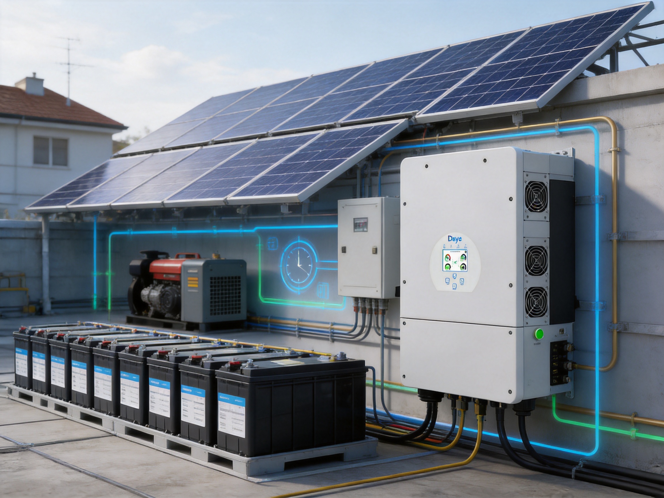
The inverter also supports energy storage from a diesel generator. This capability can be useful in remote facilities, agricultural installations, emergency power systems, and locations where the grid is weak or unavailable. Solar power can reduce generator runtime, while the battery can absorb excess generator energy or provide additional power during temporary load increases.
A generator-supported system must be designed with appropriate generator controls, synchronization, grounding, protection, and operating limits. The generator’s output quality, minimum loading requirements, fuel strategy, and maintenance schedule should all be considered. The inverter’s ability to integrate generator energy is an important foundation, but safe installation requires a complete system-level design.
AC Output Performance and Electrical Quality
The inverter is designed for a rated input and output voltage of 220/230 V with a line, neutral, and protective earth arrangement. It supports 50 Hz operation within a 45 Hz to 55 Hz range and 60 Hz operation within a 55 Hz to 65 Hz range.
Rated AC input and output active power are 7,600 W, 8,000 W, 10,000 W, and 12,000 W, depending on the model. Maximum apparent power ranges from 8,360 VA to 13,200 VA. Rated input and output currents increase with the selected power class, reaching 54.6 A input and 52.2 A output on the 12 kW version.
Maximum AC current is 38 A input and 36.4 A output for the 7.6 kW model, rising to 60 A input and 57.4 A output for the 12 kW model. Maximum continuous AC passthrough from grid to load is specified as 50 A or 60 A, depending on the product configuration.
The inverter supports power factor adjustment from 0.8 leading to 0.8 lagging. This range allows the system to respond to certain grid-support requirements and reactive power needs. Total current harmonic distortion is below 3 percent at nominal power, while DC injection current is below 0.5 percent of nominal current. These electrical quality characteristics help support compatibility with sensitive loads and utility connection requirements.
Grid compliance is addressed through a range of recognized regulations and standards, including IEC 61727, IEC 62116, CEI 0-21, EN 50549, NRS 097, RD 140, UNE 217002, OVE-Richtlinie R25, G99, and VDE-AR-N 4105. The applicable setting and certification requirements depend on the installation country and local utility.
Efficiency and Energy Yield
Efficiency has a direct effect on annual energy yield. Every conversion stage introduces some loss, so high-efficiency power electronics can help preserve more of the electricity generated by the photovoltaic array or stored in the battery.
The product family provides a maximum efficiency of 97.6 percent, Euro efficiency of 96.5 percent, and MPPT efficiency above 99 percent. Maximum efficiency describes the best conversion condition, while Euro efficiency provides a more representative weighted value across a range of operating levels. MPPT efficiency indicates the inverter’s ability to track the photovoltaic array’s available maximum power.
In real installations, total system performance also depends on module temperature, cable losses, battery round-trip efficiency, inverter loading, ventilation, dust, shading, battery state of charge, and standby consumption. Nevertheless, the stated electrical efficiency values establish a strong foundation for reducing conversion losses.
The high MPPT efficiency is particularly useful in systems with variable solar conditions. The inverter can continuously adjust the operating point of each tracker to follow the array’s changing output as irradiance and temperature vary.
Protection, Safety, and Reliability Features
Hybrid inverters operate at the intersection of high-voltage DC, high-current battery circuits, AC distribution, and digital communication. Integrated protection is therefore a central product requirement rather than an optional convenience.
The platform includes DC reverse polarity protection, AC output overcurrent protection, thermal protection, AC output overvoltage protection, AC output short-circuit protection, DC component monitoring, anti-islanding protection, a DC switch, insulation impedance detection, and residual current detection. Arc fault circuit interrupter protection is available as an option.
These functions address different failure conditions. Reverse polarity protection helps reduce risk from incorrect DC connections. Overcurrent and short-circuit protection limit fault energy on the AC side. Thermal protection responds to excessive temperature. Insulation monitoring can identify abnormal leakage paths, while residual current detection helps monitor current imbalances that may indicate a fault.
Anti-islanding protection is especially important in grid-connected operation. If utility power is interrupted, the inverter must stop feeding the public network according to applicable requirements. At the same time, a properly configured backup output can continue supplying designated loads when the system is operating in backup mode.
Surge protection is provided at Type II level on both the DC and AC sides. The product also has overvoltage categories of OVC II for DC and OVC III for AC. External surge protection and grounding design may still be required based on the site’s lightning exposure, wiring arrangement, building characteristics, and local regulations.
Environmental Protection and Mechanical Design
The enclosure has an IP65 ingress protection rating. This indicates protection against dust ingress and water jets from appropriate directions when the product is correctly installed. The rating makes the inverter suitable for many indoor and outdoor locations, although direct exposure, flooding, corrosive atmospheres, and inadequate ventilation should be avoided.
The operating temperature range is from -40°C to +60°C, with derating above 45°C. The wide range supports installations in cold climates and hot regions, while the derating requirement communicates an important design consideration: high ambient temperatures can reduce the maximum available output.
Permissible ambient humidity is 0 to 100 percent, and permissible altitude is up to 2,000 meters. Noise is specified below 45 dB, helping the product fit residential or mixed-use environments when installed in a suitable location.
The cabinet measures 420 by 670 by 233 millimeters, excluding connectors and brackets, and weighs 35.6 kilograms. Intelligent air cooling manages internal temperature during operation. The compact enclosure and moderate weight can simplify wall mounting and handling, although installers must verify wall strength, clearances, cable routing, and service access.
Digital Interface and User Control
A colorful touch LCD provides local access to operating information and settings. A built-in display is valuable during commissioning because installers can review system status without relying exclusively on a remote application or external communication device.
The communication interfaces include Wi-Fi, RS485, and CAN. Wi-Fi can support monitoring and configuration functions, while RS485 and CAN are commonly used for communication with batteries, meters, energy management devices, and other system components. The exact communication functions depend on the selected equipment and software configuration.
Communication flexibility is important in a modern energy system because the inverter rarely operates alone. Battery management systems need reliable data exchange. Smart meters may be used for export limitation or load measurement. External control systems may need access to operating data. Generator or building management interfaces may also be required in more advanced installations.
The combination of local LCD control and multiple communication interfaces provides a balance between direct service access and remote energy management. It also helps the platform adapt to different project sizes, from a single residential installation to a larger parallel inverter arrangement.
Parallel Expansion and Scalable System Architecture
The inverter supports up to 16 units operating in parallel for on-grid and off-grid applications. This is a significant scalability feature. A single unit may be sufficient for a standard property, while a multi-unit system can serve larger loads, expand battery capacity, and provide greater system redundancy.
Parallel operation can support projects where the energy requirement grows over time. An installer may begin with a smaller number of units and add capacity later, provided the final architecture, communication arrangement, protection system, and local regulations allow such expansion.
Parallel systems require careful engineering. Units must be configured with compatible firmware and settings. AC and battery cabling must be designed for balanced current sharing. Communication wiring must follow the manufacturer’s requirements. External distribution equipment must be rated for the combined current, and backup loads must be evaluated for both continuous and transient demand.
The ability to parallel multiple units provides an advantage over products restricted to single-inverter operation. It allows the same product family to address a broader range of applications without requiring a completely different platform for higher capacity.
Manufacturing Strengths and Product Development Capability
The manufacturer, Ningbo Deye Inverter Technology Co., Ltd., was founded in 2000 and operates as a technology manufacturing enterprise integrating research and development, design, production, sales, and service. This integrated structure is important for power electronics because product reliability depends on coordination among electrical design, embedded software, mechanical engineering, testing, production control, and after-sales support.
The company’s product portfolio covers photovoltaic inverters, energy storage inverters, microinverters, energy storage systems, environmental appliances, and related digital energy services. Its inverter range includes string inverters, energy storage inverters, and microinverters. This breadth allows the company to develop experience across several types of power conversion and distributed energy equipment.
For the hybrid inverter platform, manufacturing strength can be understood through several areas:
First, platform-based design supports common engineering practices across several output ratings. Shared mechanical dimensions, interfaces, protection concepts, and control functions can help improve consistency while allowing different power levels.
Second, integrated research and development enables close coordination between hardware and software. Hybrid inverters must manage photovoltaic power, battery current, grid conditions, backup loads, generator input, and communication signals in real time. These functions cannot be optimized effectively through isolated component design alone.
Third, large-scale product production can support standardized assembly, quality checkpoints, and supply-chain coordination. Consistent production processes are essential for equipment that may be installed in many climates and connected to different battery and grid systems.
Fourth, the manufacturer’s experience across residential, commercial, industrial, and utility applications can inform product development. Requirements differ greatly between a home backup system and a commercial energy storage installation, but experience in multiple segments can help identify common safety, monitoring, and service needs.
Fifth, a broad international market presence requires attention to multiple grid codes, safety requirements, documentation standards, and installer expectations. The listed grid regulations and safety standards show that the product is designed with international deployment in mind.
Manufacturing Processes Relevant to Hybrid Inverters
Advanced manufacturing for a hybrid inverter generally involves more than assembling circuit boards into an enclosure. It includes component qualification, printed circuit board assembly, power semiconductor installation, thermal interface control, firmware loading, functional testing, high-voltage testing, communication verification, enclosure inspection, and final performance validation.
Power conversion equipment requires accurate control of electrical clearances and creepage distances. High-current battery terminals require secure mechanical connections and suitable torque control. Cooling components must be installed consistently to maintain thermal performance. Sensors must be calibrated or verified so that current, voltage, temperature, and residual current measurements are reliable.
Production testing is also important because many inverter failures are linked not to the basic design, but to assembly variation, connector problems, firmware mismatch, insufficient tightening, contamination, or inadequate inspection. A mature manufacturing process therefore uses defined work instructions, traceability, inspection points, and functional test procedures.
The inverter’s integrated protection functions further increase the value of end-of-line testing. Protection responses must be evaluated in a controlled environment, while communication interfaces and display functions should be checked before shipment. These practices help reduce installation problems and improve confidence in field performance.
Manufacturing and engineering strengths do not remove the need for correct installation. Instead, they provide the foundation on which installers and system integrators can build reliable projects. Site design, commissioning, maintenance, and compliance remain essential parts of the complete energy solution.
Competitive Advantages in Practical System Design
When compared with more limited hybrid inverter products, this platform offers several practical advantages.
Its first advantage is the combination of high single-phase output and low-voltage battery support. Some high-power systems use high-voltage batteries, while some low-voltage systems are limited to lower output ratings. This product family addresses the space between those categories by providing up to 12 kW of single-phase output with battery current up to 250 A.
Its second advantage is flexibility across new and retrofit projects. The AC-coupling function allows the inverter to support existing solar systems, while DC photovoltaic inputs allow it to form the core of a new hybrid installation.
Its third advantage is multi-mode operation. On-grid, off-grid, battery, solar, grid, and generator energy can be coordinated within one architecture. This is more versatile than a product designed only for grid export or only for battery backup.
Its fourth advantage is scheduling capability. Six battery charging and discharging periods provide a more refined energy strategy than simple daytime charging and nighttime discharge.
Its fifth advantage is scalability. Up to 16 units can be paralleled, and multiple batteries can be connected in parallel. This enables system expansion for larger loads and increasing storage requirements.
Its sixth advantage is the three-MPPT option on the 10 kW and 12 kW models. Complex solar arrays can be managed with greater flexibility, which may be valuable in buildings with multiple roof surfaces or variable shading.
Its seventh advantage is integrated protection and international grid support. The combination of DC and AC protection, monitoring functions, surge protection, and recognized grid standards helps simplify the process of developing compliant system designs.
Installation Planning and Best Practices
Correct installation begins with a complete assessment of the site. The installer should determine the building’s peak and continuous loads, identify essential backup circuits, evaluate solar array orientation, inspect the proposed mounting location, and confirm the available grid connection.
Battery planning should include nominal voltage, usable capacity, continuous current, peak current, allowable state-of-charge range, temperature limits, communication protocol, and manufacturer-approved parallel configuration. The battery should be capable of supporting the inverter’s expected power demand without excessive voltage drop or premature degradation.
PV string design must remain within the inverter’s voltage and current limits under both the lowest expected module temperature and the highest expected operating temperature. Open-circuit voltage can increase in cold conditions, while operating voltage and current vary with irradiance and temperature. String lengths should be calculated rather than estimated.
AC cable and protection equipment must be selected according to the rated current, maximum current, installation method, ambient temperature, cable length, voltage drop, and applicable electrical codes. The 10 kW and 12 kW models can carry substantial single-phase current, so distribution equipment and connection points must be appropriately rated.
Ventilation and clearances should allow the intelligent air-cooling system to operate correctly. The IP65 rating does not mean that the inverter should be installed in a permanently wet, flooded, or corrosive location. Direct sunlight may increase enclosure temperature and accelerate derating, so a shaded and well-ventilated location is generally preferable.
Commissioning should verify battery communication, grid parameters, generator settings if applicable, export limitations, time-of-use schedules, backup priorities, parallel-unit configuration, and alarm reporting. The installer should also verify that the backup circuits are not overloaded by simultaneous motor starts or other high inrush loads.
Maintenance and Long-Term Operation
Hybrid inverter maintenance should include visual inspection, ventilation checks, cable and terminal inspection, event-log review, communication verification, and confirmation that the system remains within its original design limits.
Dust and debris should not be allowed to obstruct air channels. Outdoor installations should be inspected for water entry, corrosion, insect activity, physical damage, or changes in the mounting structure. Battery systems require their own maintenance program, including review of state of health, temperature, communication status, and protective alarms.
Software and firmware management should be performed according to approved procedures. In a parallel system, all units should maintain compatible versions and settings. Any change to grid parameters, battery limits, or operating schedules should be documented.
The product is supplied with a five-year warranty, with extension up to ten years depending on the installation country and applicable warranty policy. Warranty duration is only one part of lifecycle value. Availability of technical documentation, installer support, spare parts, monitoring tools, and service procedures also influences the long-term ownership experience.
Frequently Asked Questions
What type of inverter is this product?
It is a single-phase low-voltage hybrid inverter. It combines photovoltaic conversion, battery charging and discharging, grid interaction, backup operation, and energy management in one platform.
Which models are included in the product family?
The family includes 7.6 kW, 8 kW, 10 kW, and 12 kW models. The 7.6 kW and 8 kW versions are identified as AM2 models, while the 10 kW and 12 kW versions are identified as AM3 models.
What battery voltage range is supported?
The specified battery voltage range is 40 V to 60 V. The inverter supports lead-acid and lithium-ion batteries, subject to compatibility, installation, and battery management requirements.
What is the maximum battery current?
The maximum charging and discharging current is 190 A for the 7.6 kW and 8 kW models, 220 A for the 10 kW model, and 250 A for the 12 kW model.
Can several batteries be connected?
Multiple batteries can be connected in parallel, provided the battery manufacturer’s instructions and the inverter’s communication and protection requirements are followed.
Can the inverter be added to an existing solar system?
Yes. The inverter supports AC coupling, allowing it to be used to retrofit an existing solar installation. Compatibility and system control requirements must be checked before installation.
How many photovoltaic trackers does it have?
The 7.6 kW and 8 kW models have two MPPT trackers. The 10 kW and 12 kW models have three MPPT trackers.
Can the inverter operate without the utility grid?
It supports off-grid operation and can supply designated loads when configured correctly. It also provides two times rated power for 10 seconds as specified peak off-grid power, subject to the characteristics of the connected loads.
Can a diesel generator be used with the inverter?
Yes. The inverter supports storing energy from a diesel generator. Generator integration requires correct electrical design, control configuration, grounding, protection, and compliance with local requirements.
How many inverters can be connected in parallel?
Up to 16 units can be connected in parallel for on-grid and off-grid operation, subject to system design, communication, protection, and commissioning requirements.
What communication interfaces are available?
The inverter provides Wi-Fi, RS485, and CAN interfaces. These can support monitoring, battery communication, meters, and other system components depending on the equipment and configuration.
Is the inverter suitable for outdoor installation?
It has an IP65 enclosure rating and an operating temperature range from -40°C to +60°C, with derating above 45°C. The installation site must still provide suitable mounting, ventilation, environmental protection, clearances, and service access.
What protection functions are included?
Integrated functions include DC reverse polarity protection, AC overcurrent and overvoltage protection, thermal protection, AC short-circuit protection, DC component monitoring, anti-islanding protection, a DC switch, insulation impedance detection, residual current detection, and Type II AC and DC surge protection. AFCI is available as an option.
What standards are relevant to the product?
The product documentation lists several grid regulations and safety or electromagnetic compatibility standards, including IEC 61727, IEC 62116, EN 50549, IEC/EN 62109-1, IEC/EN 62109-2, and other regional requirements. The applicable certification depends on the installation market.
What is the warranty period?
The stated warranty is five years, with coverage up to ten years depending on the installation country and the applicable warranty policy.
Conclusion
The SUN-7.6/8/10/12K-SG02LP1-EU-AM2/AM3 platform is designed for users who need more than basic photovoltaic conversion. Its combination of high single-phase output, low-voltage battery compatibility, high charging and discharging current, multi-MPPT photovoltaic input, AC-coupling capability, generator support, time-based energy scheduling, and scalable parallel operation gives it a broad application range.
The product’s technical advantages are reinforced by integrated protection, high conversion efficiency, outdoor-ready enclosure design, multiple communication interfaces, and compatibility with recognized international grid requirements. These characteristics can help installers develop systems for residential backup, small commercial energy management, existing solar upgrades, remote power, and larger parallel installations.
Manufacturing strength is also an important part of the value proposition. An integrated organization combining research and development, design, production, sales, and service can coordinate the hardware, software, safety, testing, and support requirements of a modern hybrid inverter. The company’s wider experience in photovoltaic inverters, energy storage systems, microinverters, and digital energy services provides a broad technical foundation for continued product development.
As electricity prices, grid reliability expectations, and renewable energy adoption continue to evolve, flexible hybrid inverter platforms will become increasingly important. A system that can begin as a solar-plus-battery installation, operate in backup mode, integrate a generator, and expand through parallel units offers users a practical way to respond to changing energy requirements.
References
1. Product technical data for the SUN-7.6/8/10/12K-SG02LP1-EU-AM2/AM3 single-phase low-voltage hybrid inverter family.
2. Product operation and installation manual for the SUN-5/12K-SG02LP1-EU-AM3 series.
3. IEC 61727, Photovoltaic Systems—Utility Interface Characteristics.
4. IEC 62116, Utility-Interconnected Photovoltaic Inverters—Test Procedure of Islanding Prevention Measures.
5. IEC/EN 62109-1 and IEC/EN 62109-2, Safety of Power Converters for Use in Photovoltaic Power Systems.
6. EN 50549, Requirements for the Connection of Generators in Parallel with Public Distribution Networks.
7. Regional grid connection regulations and battery energy storage installation requirements applicable to the project location.
Product: SUN-7.6/8/10/12K-SG02LP1-EU-AM2/AM3

PREV:High-Performance Single-Phase Hybrid Inverter for Flexible Residential and Small-Scale Energy Systems
NEXT:Three-Phase String Inverter Technology for Reliable, Flexible Solar Power Systems
Share
Product recommendations
news recommendations
-
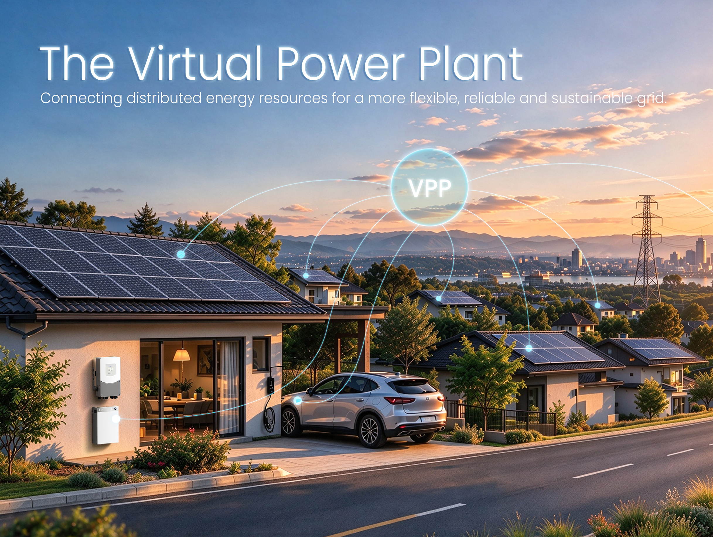 From Centralized Grids to Virtual Power Plants: The Next Evolution of the Power System
For more than a century, power systems around the world have relied on a centralized model. Large p...
-
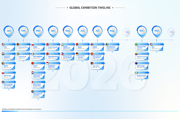 GLOBAL EXHIBITION TIMELINE
*Click to view larger image
-
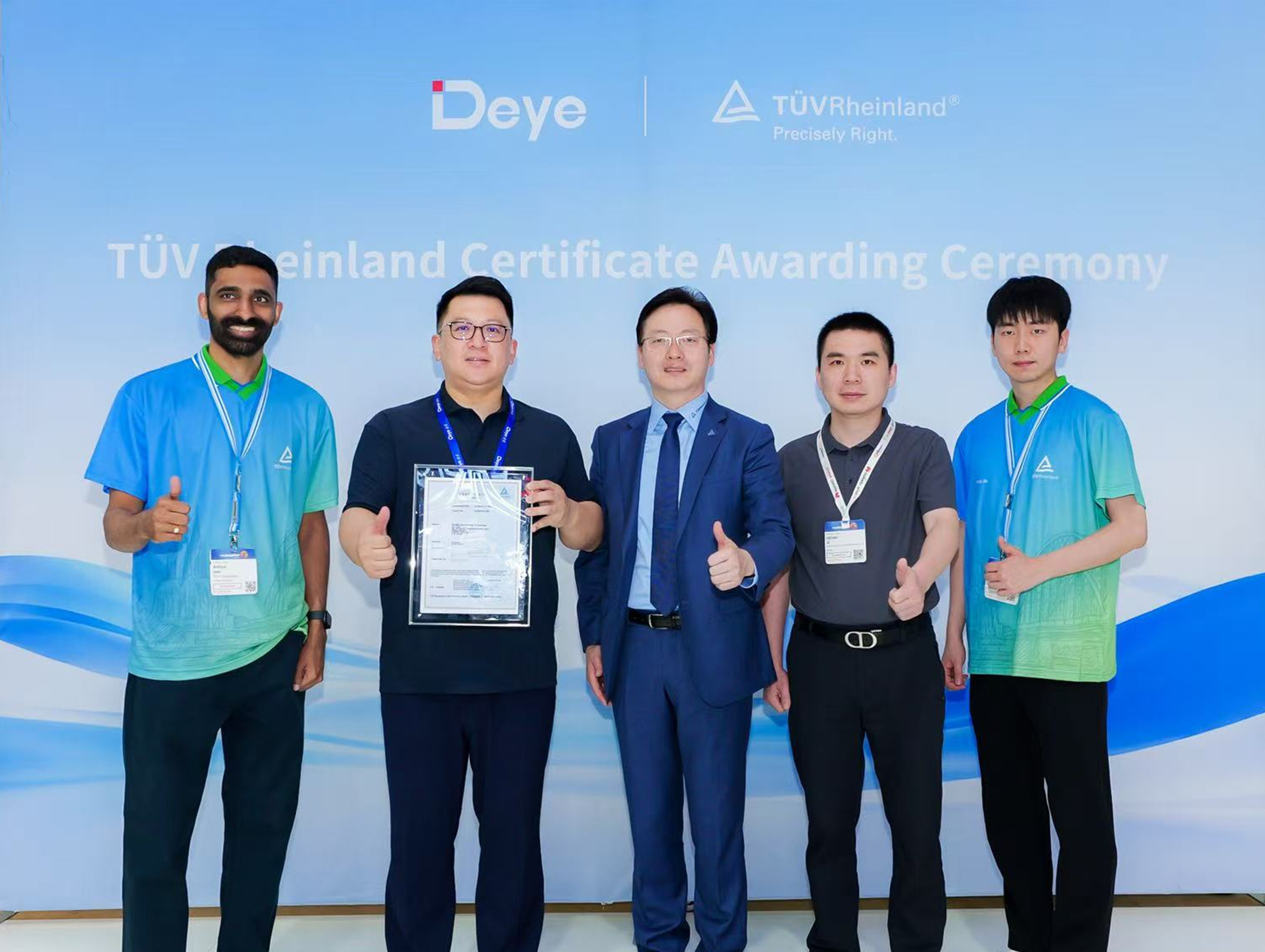 Deye Secures Multiple TÜV Rheinland Certifications at The smarter E Europe
On June 23, the opening day of The smarter E Europe 2026, Deye was officially awarded several presti...

Copyright@ 2024.Ningbo Deye Inverter Technology Co.,Ltd. All rights reserved. Solar Inverter Manufacturer
