
 Online Shop
 English
 China - 简体中文
 Global - English
 Brazil - Português
 Netherlands - Dutch
 Italy - Italiano
 Germany - Deutsch
 Spain - Español
 France - Français
 Vietnam - Tiếng Việt
 Poland - Polski
 Australia - English
 Japan - 日本語
Tan Meiling — Key Account Sales Executive, Hybrid Inverter & ESS

Advanced Four-MPPT Microinverter for High-Yield, Safe, and Intelligent Solar Installations
Modern photovoltaic systems are increasingly expected to deliver more than basic energy conversion. Installers and system owners now look for higher module compatibility, improved performance under variable sunlight, safer installation practices, reliable outdoor protection, and practical monitoring functions. The SUN-M130/160/200G3-EU-Q0-P1 series is designed to address these requirements through a compact single-phase microinverter platform with four independent maximum power point trackers, wireless communication, rapid shutdown capability, and a wide operating temperature range.
Available in 1,300 W, 1,600 W, and 2,000 W versions, this product family is intended for residential and small commercial photovoltaic systems where module-level control and flexible array design are important. Each unit can connect to four PV modules, with one independent MPPT tracker assigned to each input. This architecture allows the system to manage differences in module orientation, shading, temperature, and electrical characteristics more effectively than a conventional centralized conversion arrangement.
The product combines a maximum input current of 18 A per channel with support for modern high-power PV modules. Its 60 V maximum DC input voltage, 25–55 V MPPT voltage range, and 30–55 V full-load voltage range are suited to low-voltage module-level conversion. The result is a solar conversion solution that can be installed directly beneath the PV array while reducing the effects of mismatch and improving visibility into individual module performance.
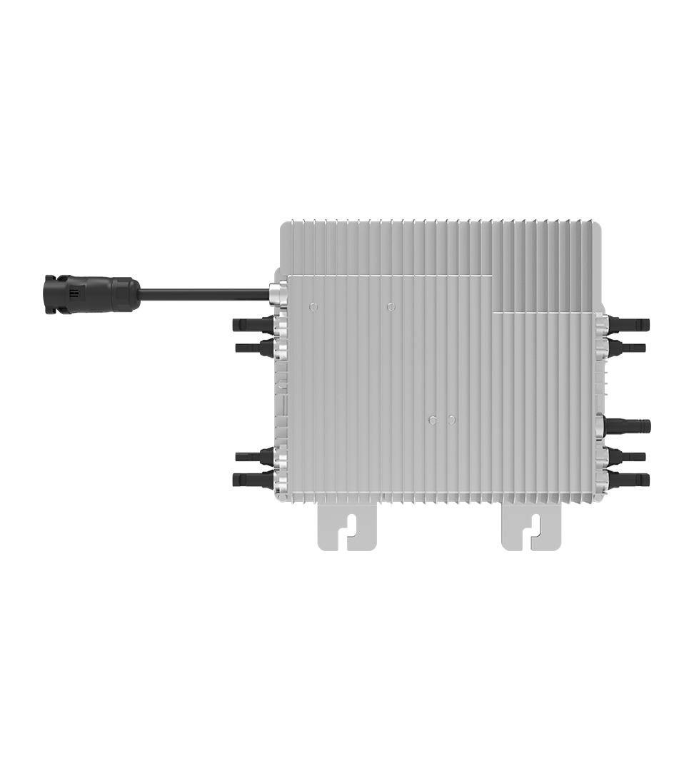
SUN-M130/160/200G3-EU-Q0-P1|1300-2000W | Single Phase | 4 MPPT | Micro Inverter
Product Overview
The SUN-M130/160/200G3-EU-Q0-P1 series is a single-phase grid-connected microinverter family. The three models share the same basic electrical and mechanical platform while offering different AC output ratings:
| Model | Rated Output Power | Maximum Output Apparent Power | Maximum Units per Branch |
|---|---|---|---|
| SUN-M130G3-EU-Q0-P1 | 1,300 W | 1,300 VA | 4 |
| SUN-M160G3-EU-Q0-P1 | 1,600 W | 1,600 VA | 4 |
| SUN-M200G3-EU-Q0-P1 | 2,000 W | 2,000 VA | 3 |
All versions provide four MPPT trackers and one string per tracker. They accept a recommended input range of 210–460 W per module for the 1,300 W model, 210–560 W per module for the 1,600 W model, and 210–700 W per module for the 2,000 W model. This allows the inverter family to accommodate a broad selection of contemporary solar modules.
The product is designed for 220 V or 230 V single-phase grids. Its rated voltage ranges include 184–242 V for 220 V operation and 195.5–253 V for 230 V operation. It can operate at both 50 Hz and 60 Hz, with corresponding frequency ranges of 45–55 Hz and 55–65 Hz. These characteristics support deployment across multiple international markets, subject to local certification and grid-connection requirements.
With a maximum efficiency of 96.5% and MPPT efficiency of 99%, the series is engineered to convert a high proportion of available PV energy into usable AC electricity. The inverter also provides a power factor greater than 0.99 and total current harmonic distortion below 3%, helping support stable and clean grid interaction.
Four Independent MPPT Trackers
One of the most important advantages of this microinverter platform is its four-channel MPPT architecture. Each of the four connected PV modules has an independent power-tracking channel. Instead of treating several panels as a single electrical block, the inverter can optimize each module separately.
This design is particularly valuable on rooftops with multiple orientations or partial shading. For example, one module may face southeast, another southwest, and two others may be installed at slightly different tilt angles. In a conventional string arrangement, the operating point of the entire string can be influenced by the weakest or most affected module. With individual module-level conversion, the impact of one module’s operating conditions is largely isolated from the others.
Independent MPPT control can also help manage variations caused by:
Different roof pitches and azimuths.
Chimneys, antennas, parapets, trees, and neighboring buildings.
Seasonal changes in sunlight angle.
Module aging and electrical mismatch.
Unequal soiling or temporary obstruction.
Different module technologies or power classes, where permitted by the system design.
The product’s 99% MPPT efficiency indicates that its control system is designed to identify and maintain the optimal operating point with minimal tracking losses. While real-world energy yield depends on installation conditions, module selection, wiring, weather, and grid availability, module-level optimization gives installers greater flexibility when designing systems for complex rooftops.
Module-Level Monitoring
Four MPPT channels also support module-level monitoring. Through the product’s WIFI communication function and a compatible monitoring platform, system owners and service personnel can obtain more detailed information about system operation. This visibility can simplify commissioning, performance verification, and troubleshooting.
In a conventional system, diagnosing an underperforming module may require electrical testing at the rooftop or the temporary disconnection of strings. A module-level architecture can help identify abnormal behavior more quickly by showing differences between individual inputs. Early detection of lower output, unexpected shutdown, or abnormal voltage can reduce service time and help prevent small problems from becoming larger performance losses.
For commercial installers, this can improve the service process across multiple customer sites. For homeowners, it can make solar production easier to understand and provide confidence that the system is operating as expected.
Compatibility with High-Power PV Modules
The series provides a maximum input current of 18 A for each of its four input channels. This characteristic is important because many new PV modules use larger cells and higher current designs to achieve greater power output. An inverter that accepts only lower input current may limit the usable capacity of such modules or force installers to select older module types.
The manufacturer states that the product can adapt to PV modules rated up to 600 W, depending on the model and system configuration. The published recommended input power ranges extend to 460 W for the 1,300 W version, 560 W for the 1,600 W version, and 700 W for the 2,000 W version. Installers should always verify the complete module electrical data, including open-circuit voltage, short-circuit current, operating current, temperature coefficients, and local design conditions, before final selection.
The 60 V maximum DC input voltage is suitable for single-module connection in a low-voltage microinverter configuration. The MPPT voltage range of 25–55 V allows the inverter to track the operating voltage of a broad range of PV modules, while the 30–55 V full-load range identifies the voltage window in which rated output can be achieved under appropriate conditions.
These specifications help simplify module selection and provide flexibility as module technology continues to develop. They also reduce the need to redesign the inverter platform when installers adopt higher-current panels for new projects.
Improved Safety at Module Level
Safety is a central consideration in PV system design. The microinverter incorporates a rapid shutdown function, which is designed to help reduce DC voltage in the array during emergency conditions or when required by applicable installation rules. Rapid shutdown can assist firefighters, maintenance technicians, and emergency responders by supporting a safer working environment around the solar array.
Because DC conversion takes place at module level, the system avoids the need for long, high-voltage DC strings running from the roof to a central inverter. This can reduce the amount of high-voltage DC cable within a building and limit the length of energized DC conductors. The final safety performance still depends on correct design, installation, labeling, protective devices, commissioning, and compliance with local electrical codes.
The product also supports a range of recognized grid-connection and safety standards. Listed grid standards include IEC 61727, IEC 62116, CEI 0-21, EN 50549, NRS 097, RD 140, UNE 217002, OVE-Richtlinie R25, G98, and VDE-AR-N 4105. Its safety and EMC references include IEC/EN 61000-6-1/2/3/4, IEC/EN 62109-1, and IEC/EN 62109-2.
Standards compliance should always be confirmed for the exact model, firmware version, market, and installation configuration. Nevertheless, the broad range of listed standards demonstrates that the product platform has been developed with international grid and safety requirements in mind.
Weather Resistance and Outdoor Reliability
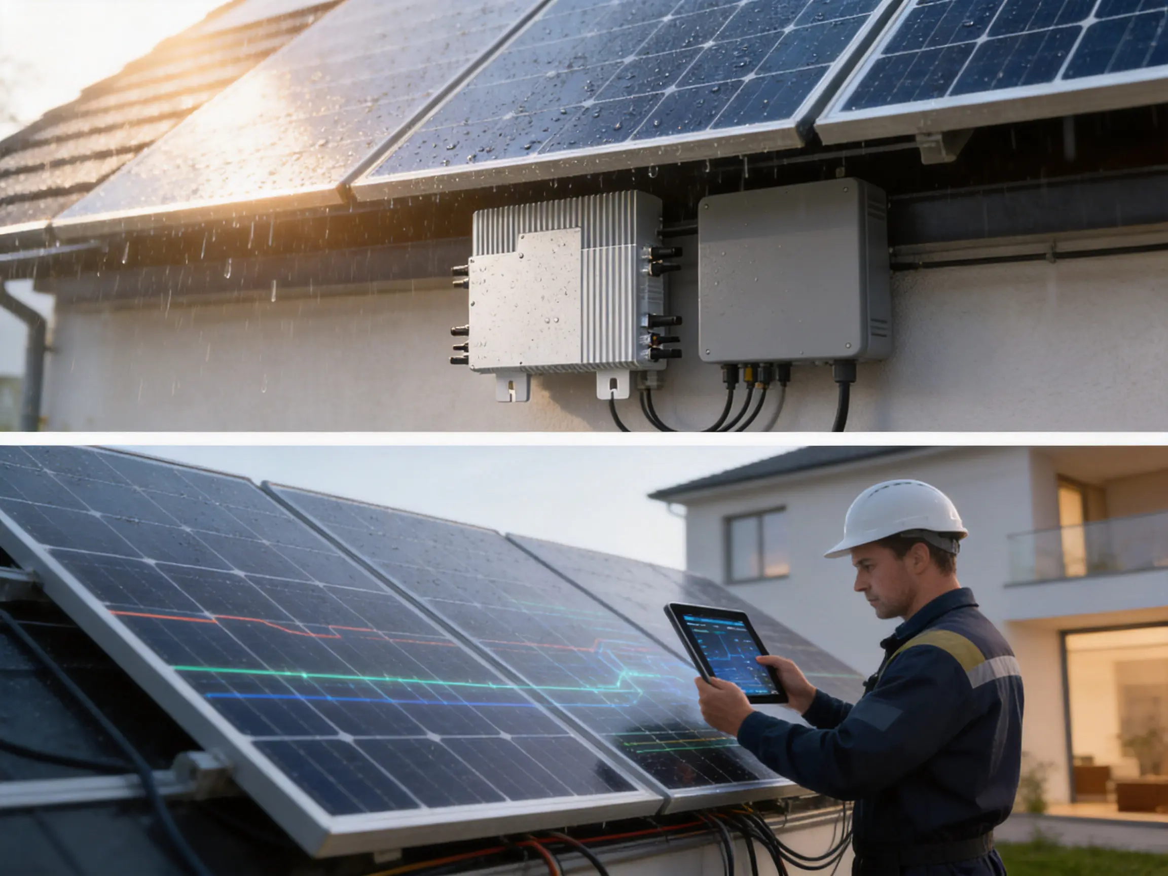
PV microinverters are commonly installed beneath solar modules, where they are exposed to outdoor temperature changes, humidity, dust, wind-driven rain, and long periods of solar heat. The SUN-M130/160/200G3-EU-Q0-P1 series uses an IP67-rated enclosure, providing a high level of protection against dust ingress and temporary water immersion under defined test conditions.
The enclosure rating is especially valuable for rooftop applications because the inverter is located in an environment that may experience condensation, rainfall, airborne particles, and occasional water exposure. Proper installation remains essential. Connectors must be fully engaged, cables must be routed correctly, and the device must be mounted according to the manufacturer’s instructions so that water does not collect around connection points.
The specified ambient operating temperature range is –40°C to 65°C, with derating above 45°C. This wide range supports installations in both cold and hot climates. The derating provision is technically important because electronic components may need to reduce output under high-temperature conditions to maintain safe operating limits. Rather than treating high temperature as an unexpected failure condition, the design acknowledges the thermal demands of rooftop operation.
The product uses free cooling rather than a forced-air fan. This approach can reduce moving parts, acoustic output, dust movement, and fan-related maintenance requirements. A fanless thermal design can also be beneficial in residential areas where quiet operation is expected. Heat management still depends on adequate ventilation, correct clearance, and appropriate mounting beneath the modules.
Mechanical Design
The cabinet dimensions are approximately 306 × 258 × 36.5 mm, excluding connectors and brackets. Its 5 kg weight provides a balance between structural robustness and manageable installation handling. The relatively compact profile allows the inverter to fit beneath many module frames without occupying excessive roof space.
Installers should verify clearance requirements, mounting strength, connector compatibility, cable length, and the mechanical characteristics of the PV module frame before installation. The inverter should not be placed where it is continuously exposed to pooled water or obstructed from dissipating heat.
Electrical Performance
The three models provide rated AC output currents of 6/5.7 A, 7.3/7 A, and 9.1/8.7 A, respectively. These paired values correspond to different nominal grid voltage conditions. The maximum AC output currents are listed at the same levels, which simplifies upstream protection and branch-circuit planning when the correct model is selected.
| Electrical Parameter | SUN-M130G3-EU-Q0-P1 | SUN-M160G3-EU-Q0-P1 | SUN-M200G3-EU-Q0-P1 |
|---|---|---|---|
| Maximum input current | 4 × 18 A | 4 × 18 A | 4 × 18 A |
| Maximum DC short-circuit current | 4 × 27 A | 4 × 27 A | 4 × 27 A |
| MPPT trackers | 4 | 4 | 4 |
| Rated output power | 1,300 W | 1,600 W | 2,000 W |
| Rated output current | 6/5.7 A | 7.3/7 A | 9.1/8.7 A |
| Maximum efficiency | 96.5% | 96.5% | 96.5% |
| MPPT efficiency | 99% | 99% | 99% |
A power factor greater than 0.99 indicates that the inverter is designed to exchange active power with the grid efficiently while limiting unnecessary reactive current under standard operating conditions. Total current harmonic distortion below 3% supports power quality and helps the system meet applicable grid requirements.
The specified DC component of grid current is below 0.5% of rated current. Limiting unwanted DC injection is important because excessive DC components can affect distribution transformers and protective equipment. The inverter’s internal control and protection systems are designed to monitor and regulate these electrical characteristics.
Branch Configuration and System Planning
The maximum number of units per branch depends on the model. Up to four units may be connected in one branch for the 1,300 W and 1,600 W models, while up to three units may be connected in one branch for the 2,000 W model. This difference reflects the higher AC current associated with the larger output version.
Branch planning should account for local electrical codes, cable ampacity, voltage drop, ambient temperature, overcurrent protection, disconnect requirements, and the permissible number of devices on a circuit. The maximum unit count is not a universal installation recommendation; it must be applied together with the specific AC trunk cable, connectors, branch protection, and grid requirements used in the project.
When a system contains multiple orientations or roof sections, installers can distribute microinverters across the array while preserving independent module-level control. This can be more practical than designing a large centralized inverter around the most difficult roof area. It may also make phased expansion simpler, provided the distribution network and local interconnection rules allow future additions.
Comparison with Conventional Inverter Architectures
The most direct alternative to a microinverter system is a string inverter. In a string system, multiple modules are electrically connected in series, and one or more central MPPT channels control the string. String inverters can be highly efficient and cost-effective for large, uniform arrays. However, their performance may be more sensitive to module mismatch and shading within each string.
A four-MPPT microinverter platform offers several advantages for small and medium rooftop systems:
First, each module has an independent conversion path. A shaded or lower-performing panel has less influence on neighboring modules than it would in a conventional series string.
Second, the system can accommodate multiple roof orientations without forcing every module into a common operating direction.
Third, module-level monitoring can provide more detailed operating information than a single string-level measurement.
Fourth, the system operates at low DC voltage at the module connection, which can simplify certain safety considerations and support rapid shutdown implementation.
Fifth, system expansion may be more modular because additional capacity can be added in discrete inverter-and-module units, subject to branch and grid limitations.
Microinverters may involve a higher per-watt equipment cost than some centralized systems, and installation includes more rooftop electronics and AC trunk connections. For that reason, the correct comparison should consider the complete project rather than the inverter purchase price alone. Roof complexity, shading, labor, monitoring needs, safety requirements, maintenance access, and long-term energy yield all influence the total value.
Advantages over Less Flexible Microinverters
Not all microinverters provide the same number of MPPT channels or the same input-current capability. Some compact products are designed around two inputs, lower-current modules, or narrower voltage windows. In contrast, the SUN-M130/160/200G3-EU-Q0-P1 series combines four MPPT trackers with 18 A input current per channel.
This combination gives the product a practical advantage when installers work with modern high-current modules or complex roof layouts. Four trackers can reduce the need to group modules with similar conditions, while high-current input capability helps preserve compatibility with newer panel designs.
The product also combines module-level monitoring, rapid shutdown, WIFI communication, IP67 protection, fanless cooling, and a 10-year warranty. These features create a more complete platform than a basic module-level inverter that performs only DC-to-AC conversion.
Performance comparisons should always be based on certified data under equivalent test conditions. Factors such as peak efficiency, weighted efficiency, startup voltage, nighttime consumption, thermal derating, monitoring availability, warranty terms, and local service support should all be evaluated before a purchase decision.
Low Nighttime Consumption
The product’s stated nighttime power consumption is 50 mW. Although this is a small value, low standby consumption contributes to efficient system operation over the complete daily cycle. Microinverters remain connected to the AC network even when solar production is unavailable, so limiting nighttime draw can reduce unnecessary energy use.
Over a long operating life, small standby losses can accumulate. Low nighttime consumption is therefore a useful supporting characteristic, particularly in systems located in regions with long winter nights or frequent periods of low irradiance.
WIFI Communication and Digital Visibility
WIFI communication provides a practical method for connecting the inverter to a monitoring environment. Digital monitoring can support initial commissioning, routine performance review, fault identification, and customer reporting.
For installers, communication helps confirm whether each unit has joined the network, whether the AC connection is available, and whether the PV inputs are producing expected power. For system owners, monitoring can show daily, monthly, and cumulative generation, depending on the capabilities of the associated platform.
Monitoring is particularly useful with module-level systems because the available data can reveal differences that would be invisible in a single whole-system production figure. A panel with persistent low output may indicate shading, soiling, a connector issue, a module fault, or a communication problem. Data should be interpreted together with weather conditions and physical inspection rather than used as the sole basis for a maintenance decision.
Wireless communication can also reduce the need for additional communication cabling in certain residential layouts. However, network planning remains important. Metal roofing, thick walls, long distances, interference, and weak router coverage can affect wireless reliability. Where a project requires high availability, installers should follow the recommended communication architecture and verify signal quality during commissioning.
Manufacturing Strength and Engineering Capability
The product is manufactured by Ningbo Deye Inverter Technology Co., Ltd., a technology manufacturing enterprise founded in 2000. The company integrates research and development, product design, production, sales, and service. This integrated structure supports coordination between engineering development and manufacturing execution.
The company operates across photovoltaic inverters, energy storage systems, dehumidification equipment, and HVAC-related products. Its inverter portfolio includes string inverters from 1 kW to 136 kW, energy storage inverters from 3 kW to 80 kW, and microinverters from 300 W to 2.2 kW. This broad product range creates opportunities to share expertise in power electronics, thermal design, control systems, embedded software, electromagnetic compatibility, and product certification.
A manufacturer with experience across several power-conversion categories can apply lessons from different operating environments. Residential microinverters require compact thermal management and high outdoor reliability. Commercial inverters require scalable power architecture and grid-support functions. Energy storage products require battery communication, bidirectional conversion, and advanced protection. Experience across these areas can strengthen the development process for new inverter generations.
The company reports that its products are sold in more than 140 countries and regions. International deployment requires attention to differing grid codes, safety standards, languages, installation practices, climate conditions, and after-sales expectations. This global exposure can support the refinement of product documentation, certification procedures, firmware behavior, and service processes.
Research and Development Integration
Advanced inverter manufacturing begins before the production line. Electrical topology, MPPT algorithms, thermal paths, enclosure design, protection circuits, communication functions, and mechanical interfaces must be developed as a coordinated system.
For this product family, the engineering challenge includes fitting four independent MPPT channels, high-current DC inputs, AC grid control, communication functions, rapid shutdown support, and thermal protection into a compact outdoor enclosure. The design must balance electrical performance with insulation distances, electromagnetic compatibility, heat dissipation, serviceability, and manufacturing consistency.
Research and development also includes compliance testing. Grid-connected inverters must be evaluated for anti-islanding behavior, voltage and frequency response, harmonic performance, leakage current, insulation, electromagnetic emissions, immunity, and abnormal operating conditions. The listed international standards indicate that the product platform has been prepared for demanding technical evaluation.
Manufacturing Process Considerations
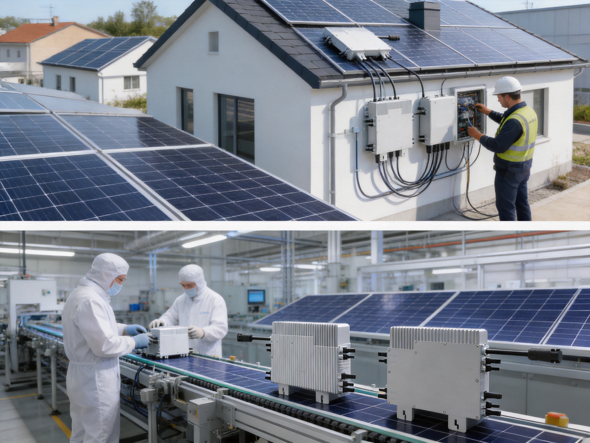
A modern microinverter production process typically includes incoming material inspection, printed circuit board assembly, power-device mounting, soldering or reflow operations, firmware programming, mechanical assembly, sealing or enclosure integration, electrical testing, functional verification, and final quality inspection.
Power electronic components must be handled with controlled processes because small variations in solder quality, component placement, thermal interface material, or connector assembly can affect long-term reliability. Automated optical inspection and electrical test systems can help identify assembly defects before products leave the factory. Functional testing can verify input tracking, AC output behavior, protection functions, communications, and response to simulated grid conditions.
For an outdoor IP67 product, enclosure and connector quality are especially important. The manufacturing process must control sealing surfaces, gasket placement, torque values, cable entry points, and connector engagement. A robust enclosure rating depends not only on the housing design but also on repeatable assembly practices and verification testing.
Thermal management is another critical production concern. Components that generate heat must be mounted with consistent contact to the heat-dissipation structure. Mechanical flatness, fastener torque, thermal interface materials, and enclosure contact all influence the final thermal path. Stable thermal performance helps the inverter operate reliably across its specified temperature range.
Quality management should continue after production. Traceability systems can associate finished products with component lots, production stations, test records, firmware versions, and inspection results. Such records help manufacturers investigate field issues, improve future production, and provide better technical support to distributors and installers.
Firmware and Control-System Development
In a modern inverter, software is as important as hardware. The firmware controls MPPT tracking, grid synchronization, output current, protection thresholds, communication, shutdown sequences, thermal derating, and fault reporting.
Four MPPT channels require coordinated control algorithms that can independently search for operating points while maintaining stable AC output. The control system must respond to changing irradiance without creating unnecessary oscillation or excessive stress on power components. It must also detect abnormal voltage, current, insulation, temperature, or grid conditions and respond according to the applicable protection strategy.
Firmware development is normally supported by laboratory simulation, hardware-in-the-loop testing, environmental tests, grid simulators, and field validation. These processes help confirm that the inverter behaves predictably during startup, normal production, low-light operation, grid disturbances, and emergency shutdown conditions.
Reliability-Oriented Product Design
Reliability is not defined by one specification alone. It is the combined result of component selection, circuit design, thermal behavior, mechanical construction, environmental protection, software stability, manufacturing controls, and installation quality.
The product’s IP67 enclosure, fanless cooling, wide ambient temperature range, low nighttime consumption, and 10-year warranty reflect a design intended for long-term outdoor use. The four models also share a common platform, which can simplify training, spare-parts planning, and installer familiarity across different project sizes.
Using a common design family can reduce the number of distinct procedures required by an installation company. Technicians can apply similar commissioning methods, monitoring practices, and troubleshooting logic to the 1,300 W, 1,600 W, and 2,000 W versions. At the same time, the output rating can be selected according to the module configuration and branch-circuit requirements.
Warranty length is one indicator of the manufacturer’s confidence in product durability, but warranty conditions must be reviewed carefully. Installation environment, registration, approved accessories, maintenance, grid conditions, and exclusions may affect warranty coverage. Customers should retain purchase records, installation documents, commissioning reports, and serial-number information.
Installation and Commissioning Guidance
Before installation, the designer should verify the PV module electrical characteristics against the inverter’s maximum input voltage, MPPT range, maximum input current, and short-circuit current. The cold-weather open-circuit voltage must remain below the inverter’s maximum DC input voltage, while the maximum current must remain within the permitted limits under the expected environmental conditions.
The installer should also confirm the AC design. This includes the nominal voltage, frequency, conductor size, protective devices, grounding arrangement, branch length, voltage drop, maximum unit count, and local utility requirements. The branch should be designed for the selected inverter model rather than assumed to be identical across the entire product family.
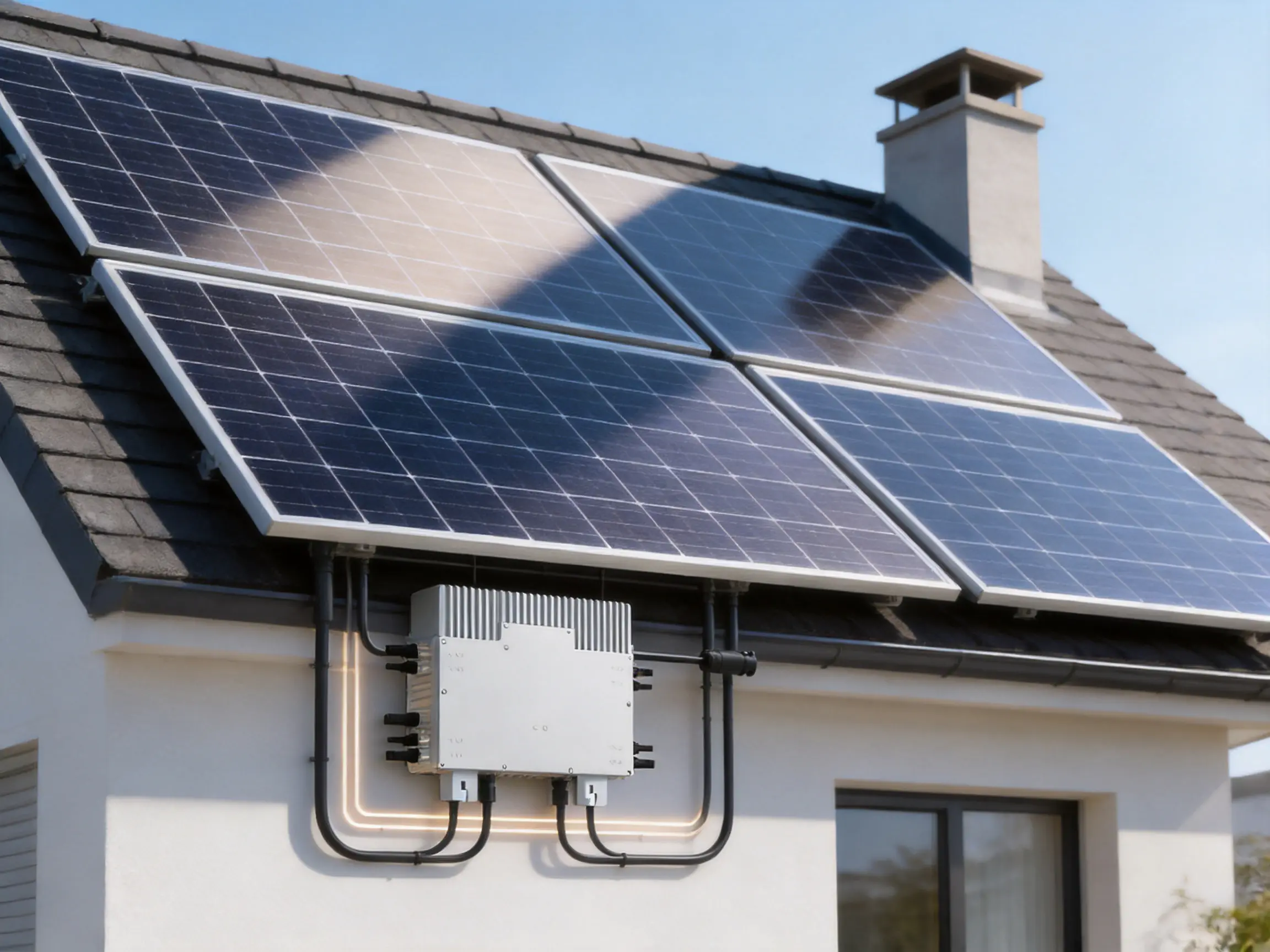
Mechanical mounting should provide a secure connection to the supporting structure. The inverter should be positioned where it can receive adequate airflow and should not be installed in a location subject to continuous standing water or excessive contamination. Connectors must be matched correctly, fully inserted, and protected from mechanical strain.
Commissioning generally includes checking polarity, confirming connector engagement, verifying grounding and bonding, energizing the AC side according to the approved procedure, connecting the PV inputs, establishing communication, and confirming that each channel reports expected values. The installer should record serial numbers, firmware information, measured voltages, communication status, and any initial warnings.
After commissioning, the system owner should receive clear instructions for monitoring, emergency shutdown, routine visual inspection, and service contact. Even a highly automated solar system benefits from periodic inspection of roof conditions, cable routing, connectors, module surfaces, and communication status.
Applications
The product family is suitable for residential rooftops where module-level monitoring, flexible orientation, and rapid shutdown are important. It can also serve small commercial buildings, garages, workshops, agricultural structures, and other installations with single-phase grid connections.
For a new residential system, the 1,300 W model may be appropriate when four moderate-power modules are used and the AC branch design supports the output. The 1,600 W model can provide additional capacity for higher-power modules, while the 2,000 W model is intended for larger module configurations and has a lower maximum unit count per branch.
The platform can be useful for retrofit projects where roof sections are irregular or where an existing system must be expanded without rebuilding a complete string arrangement. Its module-level architecture can help designers handle different roof orientations and localized shading more easily than a single-string approach.
Small commercial installations may benefit from the detailed monitoring capability. A facility manager can review output by module group and identify underperformance before it significantly affects monthly energy production. The compact form factor may also simplify installation where electrical rooms have limited space, because conversion equipment is distributed beneath the array.
Energy Yield and Economic Considerations
The value of a microinverter should be assessed through lifetime system performance rather than rated output alone. A four-MPPT design may improve energy capture on complex roofs by reducing mismatch losses. Module-level monitoring may lower troubleshooting time. Rapid shutdown may help satisfy project safety requirements. Outdoor construction and a 10-year warranty may support long-term ownership confidence.
On the other hand, the economic assessment should include equipment cost, installation labor, AC trunk components, communication equipment, service access, replacement strategy, and local permitting. A microinverter system may be more advantageous on a shaded or multi-orientation roof than on a large, uniform, unshaded commercial roof where a centralized inverter can be installed efficiently.
System designers should compare expected annual energy production using realistic shading analysis and weather data. They should also consider future expansion, module replacement, monitoring expectations, and the cost of diagnosing faults. In some projects, the additional flexibility and information provided by module-level conversion can justify a higher initial investment.
Frequently Asked Questions
What type of inverter is the SUN-M130/160/200G3-EU-Q0-P1 series?
It is a single-phase grid-connected microinverter series designed for module-level photovoltaic conversion. The family includes 1,300 W, 1,600 W, and 2,000 W rated output models.
How many PV modules can one unit connect to?
Each unit has four independent MPPT trackers and one string per tracker. It is designed to connect four PV module inputs, subject to the module electrical specifications and installation requirements.
What is the maximum input current?
The maximum input current is 18 A per channel, or 4 × 18 A for the complete four-input unit. The maximum short-circuit current is listed as 4 × 27 A.
Can the inverter work with high-power solar modules?
Yes. The product is designed to accommodate modern high-current PV modules, and the manufacturer states that it can adapt to modules up to 600 W. The exact module compatibility must be confirmed using the complete electrical data and the specific inverter model.
What is the MPPT voltage range?
The MPPT voltage range is 25–55 V. The full-load DC voltage range is 30–55 V, and the maximum DC input voltage is 60 V.
Does the product support rapid shutdown?
Yes. Rapid shutdown is included as one of the product’s key functions. The complete rapid shutdown installation must follow local regulations and the manufacturer’s instructions.
Is the inverter suitable for outdoor installation?
Yes. It has an IP67 environmental enclosure rating and an ambient operating temperature range of –40°C to 65°C, with derating above 45°C. Correct mounting, connector installation, and ventilation remain necessary.
Does the inverter use a cooling fan?
No. The product uses free cooling. A fanless design can reduce moving parts and operating noise, although the inverter still requires appropriate clearance for heat dissipation.
How is the inverter monitored?
The product supports WIFI communication. Monitoring capabilities depend on the associated communication and software environment, but the architecture is intended to support module-level visibility and system performance analysis.
What is the maximum efficiency?
The stated maximum efficiency is 96.5%, and the stated MPPT efficiency is 99%. Actual operating efficiency depends on input power, temperature, module characteristics, grid conditions, and installation design.
How many units can be connected in one branch?
Up to four units per branch are listed for the 1,300 W and 1,600 W models. Up to three units per branch are listed for the 2,000 W model. Final branch design must comply with local electrical requirements and the relevant installation instructions.
What warranty is provided?
The product information specifies a 10-year warranty. Customers should review the applicable warranty terms, registration requirements, exclusions, and service procedures for their market.
What grid standards are referenced?
The listed standards include IEC 61727, IEC 62116, CEI 0-21, EN 50549, NRS 097, RD 140, UNE 217002, OVE-Richtlinie R25, G98, and VDE-AR-N 4105. The exact approval required depends on the installation country and utility.
What makes this product different from a conventional string inverter?
Its main differences are module-level conversion, four independent MPPT trackers, module-level monitoring, low-voltage module inputs, and rapid shutdown support. These features can be especially valuable on roofs with shading, multiple orientations, or complex layouts.
Conclusion
The SUN-M130/160/200G3-EU-Q0-P1 series is designed for photovoltaic installations that require flexibility, detailed control, and practical outdoor reliability. Its four independent MPPT trackers allow each connected module to operate more independently, while the 18 A input-current rating supports compatibility with current-generation high-power PV modules.
The product combines 1,300 W, 1,600 W, and 2,000 W output options with 96.5% maximum efficiency, 99% MPPT efficiency, IP67 protection, WIFI communication, rapid shutdown, free cooling, low nighttime consumption, and a 10-year warranty. These features make the platform suitable for residential and small commercial systems where roof conditions, module mismatch, safety requirements, and monitoring quality are important considerations.
Its competitive value is strengthened by the manufacturer’s broad experience in power electronics, photovoltaic inverters, energy storage, and environmental appliances. Integrated research, product design, manufacturing, certification, and global service capabilities can support consistent product development and long-term market deployment.
As with any grid-connected electrical product, correct selection and installation are essential. Designers should verify module compatibility, branch limits, grid requirements, protection devices, environmental conditions, and local certification before specifying the inverter. When properly applied, this four-MPPT microinverter platform can provide a scalable foundation for safer, more visible, and more adaptable solar energy systems.
References
1. Product technical specification for the SUN-M130G3-EU-Q0-P1, SUN-M160G3-EU-Q0-P1, and SUN-M200G3-EU-Q0-P1 microinverter series.
2. IEC 62109-1, Safety of Power Converters for Use in Photovoltaic Power Systems—General Requirements.
3. IEC 62109-2, Safety of Power Converters for Use in Photovoltaic Power Systems—Particular Requirements for Inverters.
4. IEC 61727, Photovoltaic Systems—Characteristics of the Utility Interface.
5. IEC 62116, Utility-Interactive Photovoltaic Inverters—Test Procedure of Islanding Prevention Measures.
6. EN 50549, Requirements for the Connection of Generators in Parallel with Public Distribution Networks.
7. IEC 61000 series, Electromagnetic Compatibility Requirements and Testing Methods.
8. Manufacturer information concerning photovoltaic inverters, energy storage systems, research and development, production, and international service operations.
Product: SUN-M130/160/200G3-EU-Q0-P1|1300-2000W | Single Phase | 4 MPPT | Micro Inverter

PREV:No previous article
NEXT:High-Performance Off-Grid Solar Inverters for Reliable Energy Independence
Share
Product recommendations
news recommendations
-
 From Centralized Grids to Virtual Power Plants: The Next Evolution of the Power System
For more than a century, power systems around the world have relied on a centralized model. Large p...
-
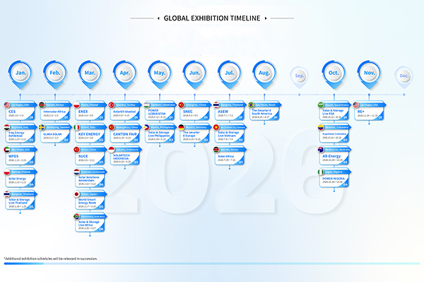 GLOBAL EXHIBITION TIMELINE
*Click to view larger image
-
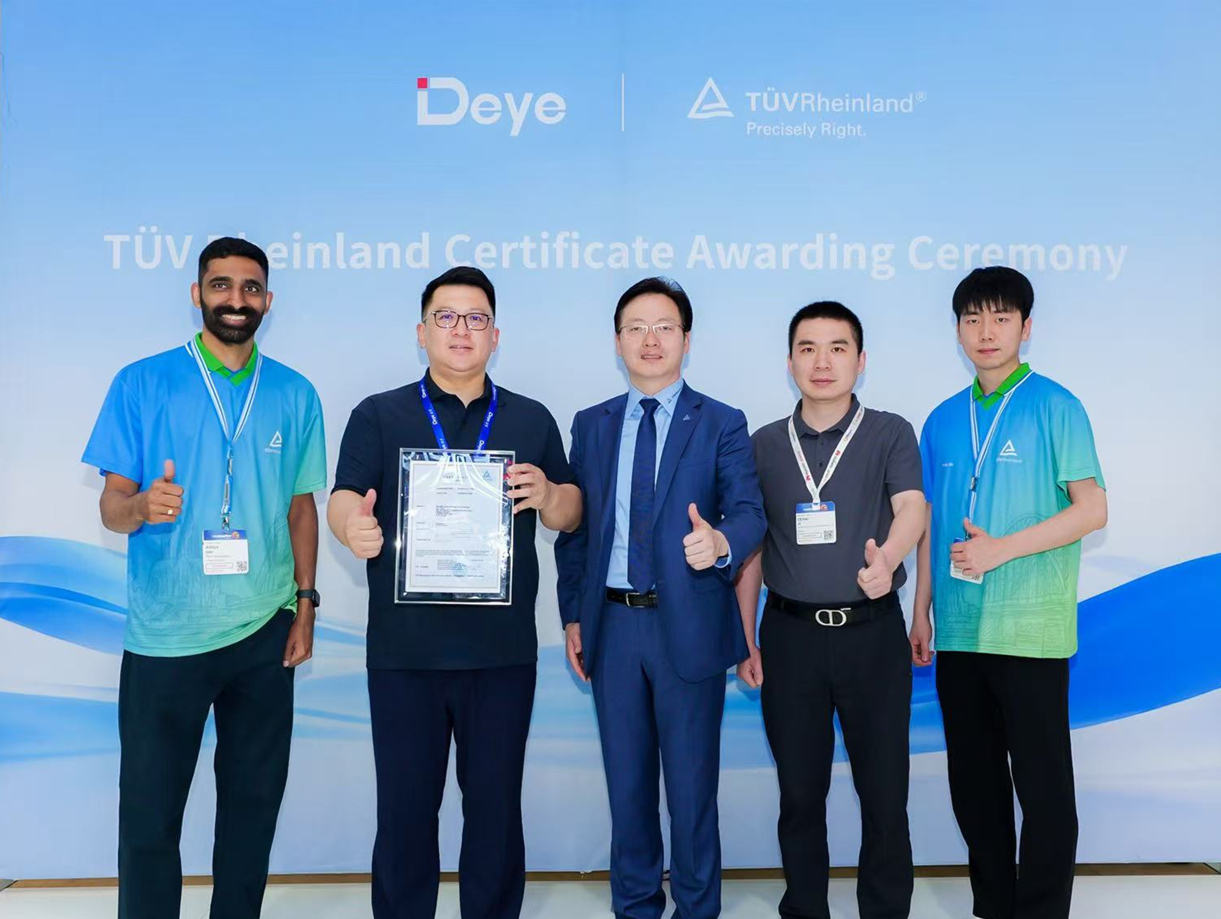 Deye Secures Multiple TÜV Rheinland Certifications at The smarter E Europe
On June 23, the opening day of The smarter E Europe 2026, Deye was officially awarded several presti...

Copyright@ 2024.Ningbo Deye Inverter Technology Co.,Ltd. All rights reserved. Solar Inverter Manufacturer
