
 Online Shop
 English
 China - 简体中文
 Global - English
 Brazil - Português
 Netherlands - Dutch
 Italy - Italiano
 Germany - Deutsch
 Spain - Español
 France - Français
 Vietnam - Tiếng Việt
 Poland - Polski
 Australia - English
 Japan - 日本語
Blog
Compact High-Performance Microinverters for Flexible Residential Solar Systems
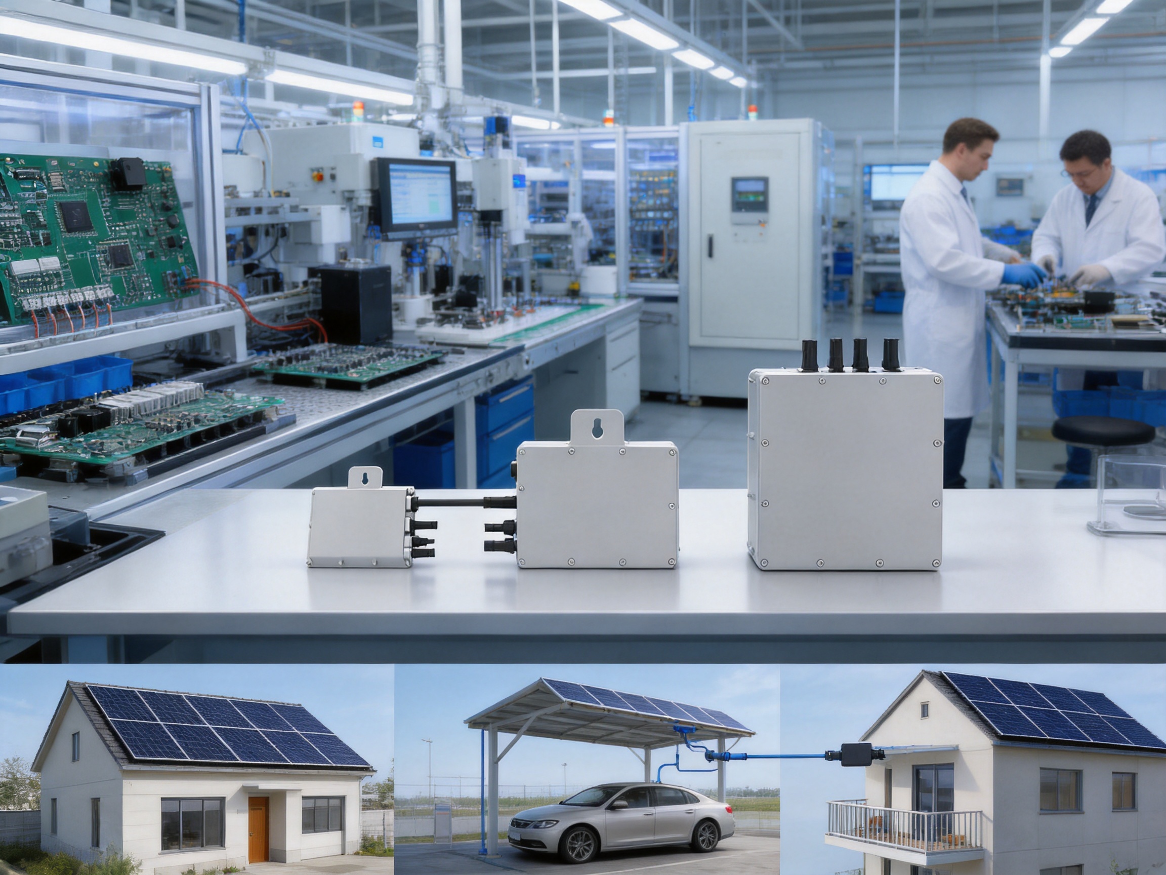
Modern photovoltaic systems are no longer designed around a single inverter whenever flexibility, safety, monitoring, and energy yield are important priorities. Module-level power conversion has become an increasingly attractive approach for residential rooftops, small commercial installations, carports, balconies, and other distributed solar applications. The SUN-M30G3-EU-Q0, SUN-M40G3-EU-Q0, and SUN-M50G3-EU-Q0 microinverters form a compact single-phase product family designed to convert the output of one solar module into grid-compatible AC power. With rated output capacities of 300 W, 400 W, and 500 W respectively, the series provides a practical choice for installations using a broad range of modern PV modules.
Manufactured by Ningbo Deye Inverter Technology Co., Ltd., the product family combines one-module architecture, a single MPP tracker, wireless communication, rapid shutdown functionality, IP67 protection, and a 10-year warranty. These features address several limitations commonly associated with traditional string inverter systems. Instead of connecting an entire array to one centralized conversion device, each microinverter works close to its assigned panel. This can improve system design flexibility, reduce the effect of partial shading, simplify expansion, and provide more detailed operational information.
The following article examines the product architecture, electrical performance, installation value, monitoring capabilities, safety features, environmental durability, and manufacturing strengths behind this microinverter family. It also explains how the three models can compete with other small single-phase inverters while helping installers and system owners select the right output rating for a specific project.
1. Product Overview and Intended Applications
A microinverter is a power conversion device installed at or near the PV module. It receives direct current from the panel, tracks the panel’s maximum power point, and converts the electricity into alternating current suitable for connection to the public grid. Because the conversion process is distributed across the array, each module can operate more independently than it would in a conventional string architecture.
The SUN-M30/40/50G3-EU-Q0 family is designed for single-phase grid-connected systems using one PV module per microinverter. The product range consists of three closely related models:
| Model | Rated Output Power | Maximum Apparent Power | Recommended PV Module Power | Maximum Units per Branch |
|---|---|---|---|---|
| SUN-M30G3-EU-Q0 | 300 W | 300 VA | 210–420 W | 17 |
| SUN-M40G3-EU-Q0 | 400 W | 400 VA | 210–560 W | 13 |
| SUN-M50G3-EU-Q0 | 500 W | 500 VA | 210–700 W | 10 |
Each unit has one DC input, one MPP tracker, and one string connection per MPP tracker. This configuration is intentionally straightforward. It allows one microinverter to be paired with one solar panel while avoiding the complexity of multi-input devices. The installer can therefore design a system according to roof geometry, module orientation, shading conditions, and future expansion plans rather than being restricted to long, uniform strings.
The family is suitable for residential rooftops where different roof surfaces may face different directions. It is also appropriate for small commercial projects, garden buildings, agricultural structures, solar carports, and distributed systems in which access to module-level data is valuable. The 300 W model can be matched with smaller or moderately sized modules, while the 400 W and 500 W versions support higher-power modules that are increasingly common in current PV markets.
Since the three models share many mechanical, communication, safety, and grid characteristics, installers can use a consistent design and maintenance approach across projects. The main selection factors are module power, expected operating voltage, desired AC output, and the maximum number of devices permitted on a branch circuit.
2. Main Technical Architecture
2.1 One Module, One Conversion Point
The most important architectural characteristic is the one-module-per-microinverter arrangement. In a conventional string system, multiple PV modules are connected in series and feed one larger inverter. A string’s current is influenced by the weakest or most affected module, especially when some panels experience shade, dirt, different orientations, or uneven aging. By contrast, a microinverter allows each panel to be tracked and converted individually.
This distributed design can offer a practical advantage in installations with complicated roof layouts. Panels can be placed on different roof planes without requiring every module to share the same orientation or inclination. The system can also be expanded in smaller increments. An owner may begin with a limited number of panels and add more later, subject to local electrical regulations and branch capacity.
The architecture also distributes conversion equipment across the array. If one microinverter experiences a fault, the remaining modules can continue to produce energy. This differs from a centralized system in which a failure of the main inverter may interrupt production from the entire array. Although every solar system still requires appropriate protection, inspection, and servicing, distributed conversion can reduce the impact of an individual device problem.
2.2 Single MPP Tracking
Each microinverter contains one maximum power point tracker. The MPPT voltage range is 25–55 V, and the maximum input DC voltage is 60 V. These values are suitable for the low-voltage output characteristics of a single PV module. The full-load DC voltage ranges are model-dependent: 30–55 V for the 300 W model, 33–55 V for the 400 W model, and 40–55 V for the 500 W model.
MPPT efficiency is specified at up to 99 percent. In practical terms, the tracker continuously adjusts its operating point to obtain the best available power from the connected module under changing irradiance and temperature conditions. Because the tracker is dedicated to one panel, the operating point of one module does not directly force the operating point of neighboring modules.
Installers should always compare the electrical characteristics of the selected module with the microinverter’s voltage and current limits. The maximum input current is 13 A, while the maximum DC short-circuit current is 19.5 A. The recommended module power ranges are 210–420 W, 210–560 W, and 210–700 W for the 300 W, 400 W, and 500 W models respectively. Proper compatibility review should include the module’s operating voltage, open-circuit voltage, operating current, short-circuit current, temperature coefficient, and expected cold-weather voltage.
2.3 Grid-Compatible AC Output
The microinverters are designed for single-phase grid connection using line, neutral, and protective earth. They support nominal grid voltages of 220 V and 230 V, with voltage ranges specified for both conditions. The rated grid frequency is 50 Hz, and the available frequency range includes 45–55 Hz for 50 Hz operation and 55–65 Hz for 60 Hz operation.
Output power is available in three levels. The SUN-M30G3-EU-Q0 delivers 300 W and 300 VA, with a rated output current of 1.4 A. The SUN-M40G3-EU-Q0 delivers 400 W and 400 VA, with a rated output current of 1.9 A or 1.8 A depending on the grid voltage. The SUN-M50G3-EU-Q0 delivers 500 W and 500 VA, with a rated output current of 2.3 A or 2.2 A. The maximum AC output current values correspond to the rated current values provided for each model.
The specified power factor is greater than 0.99, supporting efficient delivery of real power to the grid. Current harmonic distortion is below 3 percent, while the DC component injected into the grid is specified below 0.5 percent of rated current. These characteristics are important for grid quality and for meeting applicable interconnection requirements.
The product documentation lists compatibility with a wide range of grid connection standards, including IEC 61727, IEC 62116, CEI 0-21, EN 50549, NRS 097, RD 140, UNE 217002, OVE-Richtlinie R25, G98, and VDE-AR-N 4105. Final approval and installation requirements depend on the project location, utility rules, local electrical codes, and the applicable model certification status.
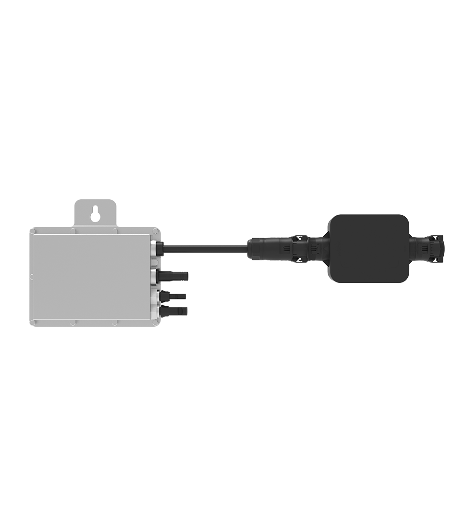
SUN-M30/40/50G3-EU-Q0 | 300-500W | Single Phase | 1 MPPT | Micro Inverter
3. Energy Yield Advantages Compared with Conventional Alternatives
3.1 Better Response to Partial Shading
Partial shading is one of the most important conditions influencing system design. Chimneys, dormers, trees, antennas, parapets, nearby buildings, and roof structures can shade only a portion of a PV array. In a string inverter system, shaded modules may affect the current available to the entire series string. Bypass diodes can reduce some effects, but energy losses can still occur.
A microinverter system handles the shaded panel at module level. A panel that receives less sunlight may produce less energy, but its operating condition is less likely to reduce the output of neighboring panels. This makes the SUN-M30/40/50G3-EU-Q0 family especially useful for roofs with irregular shading patterns or multiple orientations.
It is important to present this advantage accurately. A microinverter cannot create energy that a shaded panel does not receive, and it does not eliminate all shading losses. Its value is that the impact is more localized. The remainder of the array can continue operating closer to its own available maximum. The result may be a higher annual yield than a comparable string design in a complex shading environment.
3.2 Module-Level Optimization
With one MPPT assigned to each module, the system can accommodate differences in panel performance. Modules may vary because of manufacturing tolerance, soiling, aging, temperature, mismatch, or installation position. In a string arrangement, these differences may contribute to mismatch losses. Module-level conversion reduces the extent to which one module’s behavior governs another module’s operating point.
This feature is also valuable when panels are replaced at different times. A home or small business may add newer, higher-power modules years after the original installation. A microinverter-based system can make this process more manageable because the new module can be paired with a suitable microinverter rather than being forced into an existing string with identical electrical characteristics.
3.3 High Conversion Efficiency in a Compact Format
The maximum efficiency of the product family is specified at 96.5 percent, with MPPT efficiency up to 99 percent. Efficiency is only one part of annual energy performance, but it remains an important consideration because conversion losses occur every day the system is operating.
The compact design combines power electronics, control functions, communication capability, and protective features in a housing measuring 144 × 189 × 31.5 mm, excluding connectors and brackets. The stated weight is 1.7 kg. This relatively compact form factor can simplify handling during rooftop installation and reduce the physical footprint beneath the module.
Free cooling is used instead of a mechanically driven fan. A fanless approach can reduce moving-part wear, acoustic output, and maintenance requirements. It also avoids a common failure mechanism associated with fans operating in dusty, hot, or humid environments. The unit is specified for ambient temperatures from –40°C to 65°C, with derating above 45°C. Installers should allow adequate airflow and avoid placing the device where heat can accumulate.
4. Safety, Protection, and System Reliability
4.1 IP67 Enclosure Protection
The microinverter has an IP67 environmental rating. This indicates protection against dust ingress and temporary immersion under defined test conditions. For rooftop equipment exposed to rain, airborne particles, humidity, and changing weather, enclosure protection is a fundamental reliability requirement.
IP67 protection does not mean that installation quality is unimportant. Connectors must be correctly mated, unused connections must be sealed in accordance with the installation instructions, and cable routing should prevent mechanical stress or water accumulation. The equipment should also be installed in a position that avoids unnecessary exposure to standing water, corrosive substances, and excessive heat.
4.2 Rapid Shutdown Function
The series includes a rapid shutdown function. Rapid shutdown is intended to help reduce PV conductor voltage during emergency conditions or servicing, subject to the complete system design and the applicable regulations. This feature can improve the safety of firefighters, maintenance technicians, and emergency responders by supporting controlled de-energization of the PV array.
Rapid shutdown performance depends on the associated equipment, wiring arrangement, communication process, and local requirements. The product information identifies SUN-MI-RELAY-01 as the network and system protection device associated with the microinverter system. Designers should confirm the required protection architecture, compatibility, and installation procedure before commissioning.
4.3 Electrical and EMC Standards
The listed safety and EMC standards include IEC/EN 61000-6-1, IEC/EN 61000-6-2, IEC/EN 61000-6-3, IEC/EN 61000-6-4, IEC/EN 62109-1, and IEC/EN 62109-2. These standards address areas such as electromagnetic compatibility and the safety of power conversion equipment used in photovoltaic systems.
Compliance with recognized standards helps manufacturers evaluate insulation, electrical clearances, protective measures, electromagnetic emissions, immunity, and abnormal operating conditions. For installers and system owners, standards-based design provides a clearer technical basis for selecting equipment and completing grid interconnection documentation.
4.4 Ten-Year Warranty
The product family is supplied with a 10-year warranty. A long warranty period can reduce perceived ownership risk, particularly because microinverters are installed across the roof and may be more difficult to access than a single wall-mounted inverter. Warranty terms, exclusions, registration requirements, labor coverage, and service procedures should be reviewed in the purchase documentation.
The warranty also reflects the importance of long-term product design. A rooftop power electronic device must tolerate thermal cycling, vibration, humidity, ultraviolet exposure, and electrical transients over many years. Enclosure protection, fanless cooling, component selection, sealing, testing, and quality control all contribute to reliable field operation.
5. Monitoring and Digital System Management
Wireless and Wi-Fi communication are included among the product features. Communication enables the system to report operational information and supports module-level monitoring. Instead of viewing only the total output of an entire string, the installer or owner can identify how individual microinverters and panels are performing.
Module-level monitoring offers several practical benefits. A sudden reduction in one panel’s output may indicate soiling, shading, a connector problem, wiring damage, or a device fault. When the system provides data for each module, troubleshooting can begin with a more precise understanding of the problem area. This can reduce diagnostic time and help avoid unnecessary replacement of healthy equipment.
Monitoring is also useful for verifying system commissioning. After installation, the installer can compare the expected output of each module with actual production under similar irradiance conditions. Differences may reveal incorrect connections, shading that was not identified during the design stage, or a mismatch between the selected module and microinverter.
For homeowners, a monitoring platform can make solar production easier to understand. Daily, monthly, and annual generation trends can be compared with household consumption or utility bills. For commercial users, monitoring may help document energy performance and identify operational changes over time.
The supplied information refers to Wi-Fi communication and describes the wider company ecosystem as including the Deye Cloud App. Actual communication accessories, network requirements, commissioning steps, firmware functions, and available data fields should be confirmed for the specific market and product configuration. A stable wireless network and correct device registration remain important for dependable remote monitoring.
6. Installation Flexibility and Branch Design
6.1 Simplified Array Planning
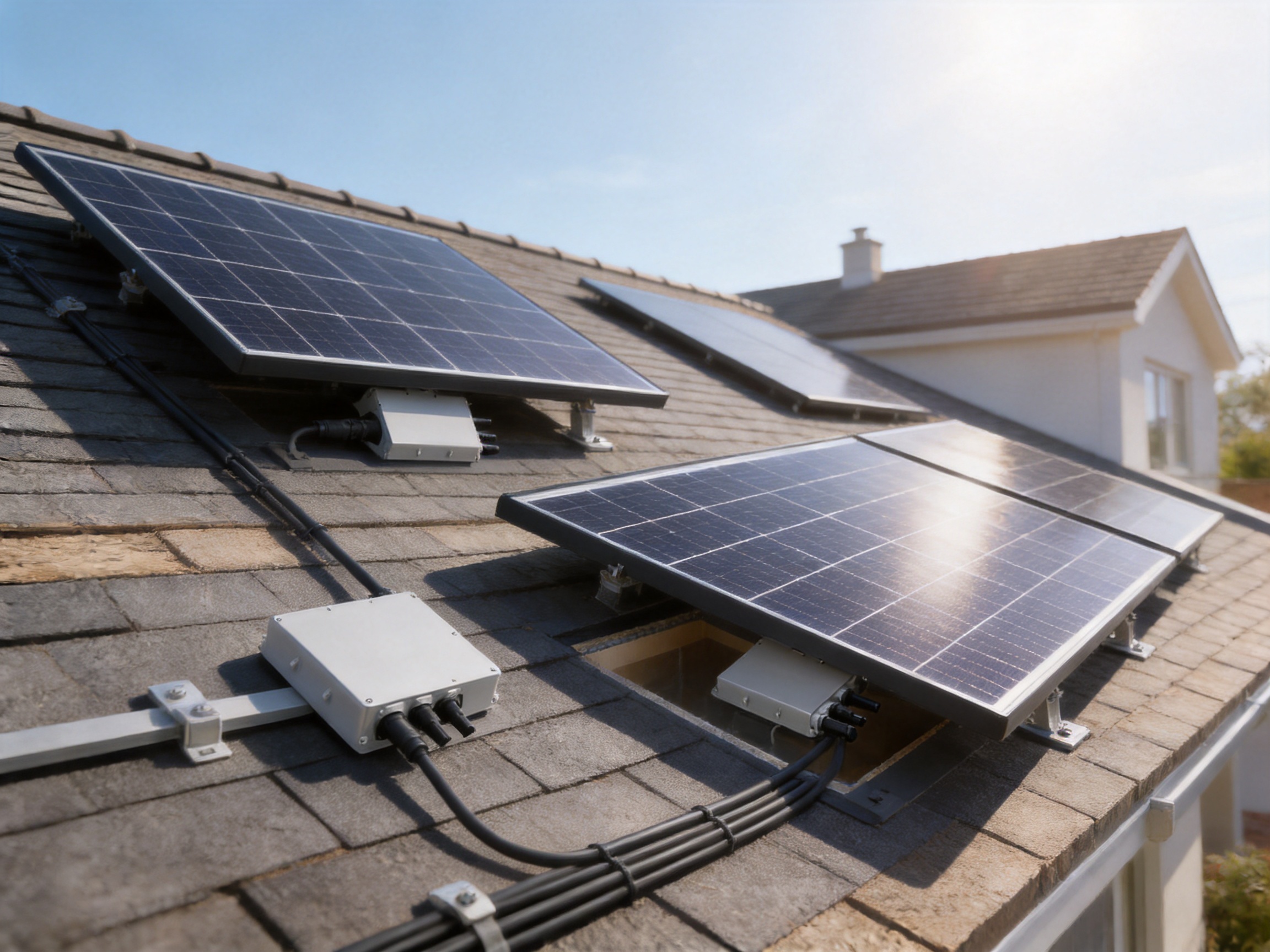
Microinverters can simplify array planning on roofs with several orientations or uneven module counts. Each panel can be assigned its own conversion device, so designers do not need to organize every module into long series strings with similar voltage and current characteristics. This can be particularly valuable on small roofs where traditional string arrangements may leave unused space or require multiple MPPT inputs.
The product family uses one input and one MPPT tracker. The installation process can therefore be standardized: mount the microinverter beneath the assigned panel, connect the DC input, link the AC trunk cable, complete grounding and communication connections, and commission the system according to the installation manual. Exact procedures must follow the manufacturer’s instructions and local electrical regulations.
6.2 Maximum Units per Branch
Branch capacity is an essential design consideration. The specified maximum number of units per branch is 17 for the SUN-M30G3-EU-Q0, 13 for the SUN-M40G3-EU-Q0, and 10 for the SUN-M50G3-EU-Q0. These limits reflect the AC output current and the requirements of the branch circuit.
| Model | Rated Current at 220 V / 230 V | Maximum Units per Branch | Approximate Maximum Branch Power at Rated Output |
|---|---|---|---|
| SUN-M30G3-EU-Q0 | 1.4 A / 1.4 A | 17 | 5.1 kW |
| SUN-M40G3-EU-Q0 | 1.9 A / 1.8 A | 13 | 5.2 kW |
| SUN-M50G3-EU-Q0 | 2.3 A / 2.2 A | 10 | 5.0 kW |
The approximate branch power values are calculated from the rated output multiplied by the maximum recommended unit count. They are not a substitute for electrical design. Cable size, protective devices, voltage drop, ambient temperature, installation method, local code, and utility requirements must all be considered. Branch protection and system coordination should be completed by a qualified professional.
6.3 Expansion and Lifecycle Advantages
Distributed systems can be expanded in manageable steps. A property owner may install an initial group of modules and later add more panels to another roof section, garage, or carport. Because the system does not necessarily depend on one large central inverter sized for the entire final array, staged expansion can be more convenient.
Microinverters can also support phased replacement. If one device reaches the end of its service life, the issue is localized to the affected module position. A replacement can be selected according to the current product range and system compatibility. The complete array does not automatically need to be shut down or replaced because of a single unit failure.
7. Choosing Between the 300 W, 400 W, and 500 W Models
7.1 SUN-M30G3-EU-Q0
The 300 W model is designed for modules with recommended STC ratings from 210 W to 420 W. It provides 300 W of rated AC output and allows up to 17 units per branch. This model can be suitable for smaller modules, legacy panels, compact rooftop systems, and projects where the installer wants a relatively high number of modules on each branch.
Its full-load DC voltage range is 30–55 V. When paired with a compatible module, it can offer a balanced relationship between panel power and AC capacity. The module’s electrical data should be reviewed carefully, especially if the project uses high-current modules or operates in unusually cold conditions.
7.2 SUN-M40G3-EU-Q0
The 400 W model supports recommended module power from 210 W to 560 W and provides 400 W of rated AC output. With a maximum of 13 units per branch, it is a versatile middle option for many residential and small commercial projects.
The full-load DC voltage range is 33–55 V. This model may be appropriate where the selected panel has a higher power rating than the typical module used with the 300 W version, but where a 500 W microinverter would not be necessary. It can provide a practical balance between output capacity, branch size, and equipment cost.
7.3 SUN-M50G3-EU-Q0
The 500 W model is intended for modules with recommended STC power from 210 W to 700 W. It provides 500 W of rated AC output and permits up to 10 units per branch. This version is designed for larger, high-power PV modules and may help reduce clipping when the module’s output is closer to the upper end of the supported range.
The full-load DC voltage range is 40–55 V. This requirement makes module compatibility especially important. The 500 W version should be selected only when the module’s voltage characteristics remain within the permitted operating range across the expected temperature conditions.
7.4 The Importance of Clipping Analysis
PV modules rarely operate at their nameplate STC rating throughout the day. Real-world irradiance, temperature, orientation, dust, and system losses influence production. Some designs intentionally pair a PV module with an inverter whose AC rating is lower than the module’s STC rating. This practice, known as DC-to-AC oversizing, can improve equipment utilization and may be economically beneficial.
However, excessive oversizing can increase clipping, meaning potential DC power is limited by the inverter’s AC output ceiling. The best model depends on the local climate, roof orientation, tilt angle, shading conditions, module electrical characteristics, and energy price structure. Installers should use a suitable design tool or production model rather than selecting an inverter based only on the module’s nominal wattage.
8. Manufacturing Strengths and Quality-Oriented Production
The technical performance of a microinverter depends not only on the circuit design but also on how consistently that design is manufactured. Ningbo Deye Inverter Technology Co., Ltd. describes itself as a comprehensive technology manufacturing enterprise integrating research and development, design, production, sales, and service. This vertically connected structure can help shorten communication paths between engineering, production, testing, and customer support.
The company was founded in 2000 and became listed on the Shanghai Stock Exchange in 2021. Its business covers photovoltaic inverters, energy storage systems, dehumidification equipment, HVAC products, and related energy technologies. The supplied company information states that its products are sold in more than 140 countries and regions and that its inverter portfolio includes microinverters from 300 W to 2.2 kW, string inverters from 1 kW to 136 kW, and energy storage inverters from 3 kW to 80 kW.
8.1 Research and Development Integration
Microinverters require close coordination between power electronics, embedded controls, thermal design, communication, protection, and grid compliance. An organization with dedicated research and development resources across several inverter categories can apply experience from one product line to another. Knowledge of grid connection requirements, switching devices, control algorithms, monitoring platforms, and safety design can support the development of compact distributed products.
The SUN-M30/40/50G3-EU-Q0 family illustrates this integrated approach by combining MPPT control, DC-to-AC conversion, wireless communication, rapid shutdown capability, grid protection, EMC compliance, and environmental sealing in a small enclosure. These functions must operate together without compromising reliability or installation simplicity.
8.2 Production Consistency
High-volume manufacturing can provide advantages when it is supported by controlled processes and suitable testing. Repeatable assembly procedures help maintain consistent soldering, connector installation, sealing, cable routing, and mechanical fastening. Automated or semi-automated inspection can support the detection of component placement errors, soldering defects, and assembly deviations.
For a rooftop microinverter, process consistency is particularly important because the device may remain exposed to outdoor conditions for many years. A small weakness in an enclosure seal, connector interface, or thermal connection can become more significant after repeated temperature cycles. Quality-oriented production therefore needs to address both electrical performance and environmental durability.
8.3 Testing and Validation
A robust manufacturing process normally includes multiple stages of quality verification. Typical areas of evaluation for a product of this type include input voltage behavior, MPPT operation, AC output stability, insulation, grounding continuity, communication performance, protective response, thermal operation, and abnormal-condition testing.
Compliance testing against IEC and EN standards provides an additional framework for evaluating safety and electromagnetic compatibility. The listed standards for this product family indicate that the design has been developed with recognized international requirements in mind. Installers should nevertheless confirm the certificates and declarations applicable to the intended sales region.
8.4 Global Service and Product Ecosystem
A manufacturer’s strength is also reflected in its ability to support products after delivery. The company provides international sales and service channels and has developed a broader digital ecosystem around monitoring and energy management. This can be valuable for distributors and installers who need product documentation, commissioning guidance, replacement support, firmware information, and technical communication.
The wider product portfolio is another advantage. A supplier that offers microinverters, string inverters, hybrid inverters, off-grid inverters, battery energy storage systems, EV charging equipment, and monitoring accessories may be able to support projects as their energy requirements grow. A residential customer can potentially begin with a grid-connected microinverter system and later consider storage or electric vehicle charging without changing to an entirely unrelated supplier ecosystem.
9. Advantages Over Competing Microinverter Approaches
Competition in the microinverter market includes products with different input counts, output ratings, monitoring systems, enclosure designs, warranties, and grid approvals. The SUN-M30/40/50G3-EU-Q0 family has several characteristics that can make it attractive compared with basic or less flexible alternatives.
9.1 A Clear Three-Model Range
Some product families offer only one output size, forcing installers to accept excessive clipping or use a larger device than necessary. This series offers 300 W, 400 W, and 500 W options with closely related specifications. The choice can therefore be matched more accurately to the selected module.
The three-model structure also helps distributors manage product inventory and installers standardize their design practices. A company can use the same basic installation and monitoring approach while selecting different power levels for different roof sections.
9.2 Module-Level Monitoring Without a Complex Multi-Input Design
Some competing microinverters use multiple inputs to serve two, four, or more panels. Multi-input products can reduce the number of physical inverter units, but they may also introduce more complicated installation decisions. The single-input architecture of this family provides direct correspondence between one panel and one monitoring point.
This one-to-one relationship can make fault identification and system mapping easier. It may also be preferable for roofs where panels are separated by structural features or installed with different orientations. The trade-off is that more microinverter units are required for a given array, so the project should be evaluated based on total system cost, labor, cable requirements, and long-term service considerations.
9.3 Outdoor Durability and Fanless Operation
An IP67 enclosure, free cooling, and a wide operating temperature range provide a strong outdoor equipment profile. In comparison with products that use less robust enclosure ratings or fan-based cooling, the design may offer lower exposure to dust-related fan problems and fewer moving parts.
Fanless operation does not remove the need for thermal management. The device must still be installed according to clearance and ventilation requirements, and output derating above 45°C must be recognized during system design. Nevertheless, the absence of a mechanical cooling fan can support quiet operation and potentially reduce maintenance demands.
9.4 Broad Grid Standard Support
The listed grid standards cover several European and international markets. Broad standard support can simplify product selection for installers serving multiple regions. It can also indicate that the inverter platform has been engineered to address different grid voltage, frequency, and protection requirements.
Standards support should not be interpreted as universal approval for every country. Grid authorities may require specific certificates, settings, firmware versions, or external protection equipment. Even so, a product developed with a broad standards portfolio may provide a stronger starting point than a device intended for only one narrow market.
9.5 Integrated Safety Functions
Rapid shutdown capability, grid protection compatibility, DC and AC monitoring, and recognized safety standards contribute to a more complete system design. Competitors may offer some of these functions as optional accessories, whereas the product information identifies them as part of the overall solution or compatible system architecture.
10. Practical Design and Installation Considerations
Correct sizing begins with the PV module datasheet. The module’s maximum power voltage should fall within the microinverter’s MPPT range under relevant operating conditions. The module’s open-circuit voltage must remain below the 60 V maximum input voltage, including the effect of the lowest expected temperature. The module’s operating and short-circuit currents must also remain within the product limits.
The installer should consider the electrical environment at the site. Grid voltage, frequency, phase arrangement, protective earthing, branch circuit ratings, isolation requirements, cable lengths, voltage drop, and local utility rules all influence the final design. The maximum branch unit count should never be exceeded, and the branch protection device should be selected according to the complete circuit calculation.
Mechanical mounting is equally important. The microinverter should be firmly secured beneath the PV module or on an approved support structure. Connectors should be protected from direct exposure to standing water and should not be left under tension. Cables should be supported so that wind movement does not transfer stress to the connectors.
Because the ambient temperature range extends from –40°C to 65°C, the product is designed for demanding climates. However, output derating above 45°C means that designers should assess the installation location’s thermal conditions. A dark roof, restricted airflow, or direct contact with heat-retaining materials can raise the microinverter’s operating temperature.
Commissioning should include visual inspection, polarity verification, grounding checks, AC voltage confirmation, communication setup, device mapping, and production verification. The installer should record serial numbers and physical locations so that future service personnel can identify the corresponding module and microinverter quickly.
11. Maintenance and Long-Term Operation
Microinverter systems generally require limited routine maintenance, but periodic inspection remains advisable. Module surfaces should be checked for excessive dirt, bird deposits, physical damage, and new shading sources. Cables and connectors should be inspected for signs of ultraviolet degradation, animal damage, water entry, or mechanical strain.
Monitoring data can support condition-based maintenance. If one module’s production gradually falls below the output of comparable neighboring panels, the owner or installer can investigate the cause. A difference may result from shade or soiling rather than an inverter problem, so digital data should be combined with a physical inspection.
The 50 mW night-time power consumption specified for the microinverter is very low. This helps limit standby energy use when the PV modules are not producing. During normal operation, the device manages conversion and communication automatically, while the monitoring platform can provide information about production and system status.
In the event of a fault, module-level architecture can make troubleshooting more targeted. The affected unit can be isolated from the rest of the array for testing, subject to safe work procedures. Replacement should be performed only by qualified personnel using compatible equipment and following the manufacturer’s instructions.
12. Sustainability and Lifecycle Value
The value of a solar inverter should be considered over its complete operating life rather than only its purchase price. A durable enclosure, efficient conversion, low standby consumption, fanless cooling, and a long warranty can contribute to lifecycle value. Reliable module-level monitoring may also reduce the time required to locate faults and maintain production.
Microinverters can support incremental system growth, which may prevent premature oversizing of the initial installation. A homeowner can install an appropriately sized system today and add modules later as electricity demand increases. This is useful for properties that may later adopt heat pumps, electric vehicles, home offices, or battery storage.
Distributed conversion also offers resilience at the system level. A single device fault does not necessarily stop every panel from producing. Although this does not eliminate the need for system-level protection and maintenance, it can help preserve partial generation while a repair is arranged.
13. Recommended Applications
The 300 W model is well suited to smaller PV modules and compact residential installations. It may be useful where branch capacity for a larger number of microinverters is desirable or where the array contains moderate-power panels.
The 400 W model is a flexible option for mainstream residential panels and small commercial arrays. It can provide a balanced solution where module ratings, roof space, and branch design fall between the requirements of the 300 W and 500 W products.
The 500 W model is appropriate for high-power modules and installations where a larger AC output per panel is important. It can be particularly attractive for new projects using larger-format panels, provided that the module voltage and current characteristics meet the inverter specifications.
Across the family, the products are appropriate for roofs with mixed orientations, small shaded areas, phased installations, and projects where module-level monitoring is a priority. They may be less suitable when a very large, uniform array requires the lowest possible equipment count and a centralized inverter approach offers a clear economic advantage. Good system design depends on the site rather than on one inverter architecture being universally superior.
14. Frequently Asked Questions
Q1: What is the main difference between these microinverters and a traditional string inverter?
A traditional string inverter receives power from a series-connected group of PV modules. The products in this family are installed at module level, with one microinverter assigned to one panel. This can improve design flexibility, limit the effect of partial shading, and provide individual module monitoring. The trade-off is that more inverter units may be required across the array.
Q2: How many PV modules can one microinverter connect to?
Each SUN-M30G3-EU-Q0, SUN-M40G3-EU-Q0, and SUN-M50G3-EU-Q0 is designed for one PV module. Each unit has one DC input, one MPP tracker, and one string per MPP tracker.
Q3: Which model should be used with a 500 W solar panel?
The 400 W or 500 W model may be considered, depending on the panel’s voltage, current, site conditions, and the desired DC-to-AC ratio. The SUN-M40G3-EU-Q0 supports recommended module power up to 560 W, while the SUN-M50G3-EU-Q0 supports up to 700 W. The final selection should include a clipping analysis and a complete electrical compatibility check.
Q4: Can the microinverters be used on roofs with different orientations?
Yes, the module-level architecture is well suited to arrays with different roof orientations and inclinations. Each panel has its own MPPT and conversion point, reducing the need to place differently oriented panels in the same string. Local regulations and the installation manual still govern the final design.
Q5: Are the microinverters suitable for outdoor installation?
Yes. The units have an IP67 enclosure rating and an ambient operating range of –40°C to 65°C. They use free cooling and are designed for outdoor PV applications. Installation must still follow the specified mounting, connector, ventilation, and environmental requirements.
Q6: What happens if one microinverter stops working?
The affected module may stop producing normally, but other correctly operating microinverters can continue to generate electricity. Module-level monitoring can help identify the affected device. Service work should be completed by qualified personnel after following the required isolation and safety procedures.
Q7: Does the product include rapid shutdown?
Rapid shutdown functionality is listed among the product features. The complete rapid shutdown system may require compatible network or protection equipment, including the listed SUN-MI-RELAY-01 device. The exact arrangement should be confirmed against local regulations and the applicable installation documentation.
Q8: What communication method is provided?
The product information lists Wi-Fi and wireless communication. This supports system communication and module-level monitoring. Network setup, monitoring platform availability, and accessory requirements may vary by region and product configuration.
Q9: How efficient are the microinverters?
Maximum efficiency is specified at 96.5 percent, and MPPT efficiency is specified at up to 99 percent. Actual operating efficiency varies with input power, module voltage, temperature, and grid conditions.
Q10: What warranty is provided?
The microinverter family is listed with a 10-year warranty. Buyers should review the official warranty document for coverage conditions, registration requirements, exclusions, replacement procedures, and any regional terms.
Q11: What is the maximum number of units on one branch?
The maximum recommended branch quantity is 17 units for the 300 W model, 13 units for the 400 W model, and 10 units for the 500 W model. These limits must be applied together with local electrical codes, branch protection requirements, cable ratings, and voltage-drop calculations.
Q12: Can the system later be combined with energy storage or EV charging?
The microinverter is a grid-connected PV conversion product. A broader energy system may incorporate storage or EV charging through compatible equipment and an appropriate energy management design. Such integration requires a separate system assessment covering power flow, backup requirements, communications, protection, and local approvals.
15. Conclusion
The SUN-M30G3-EU-Q0, SUN-M40G3-EU-Q0, and SUN-M50G3-EU-Q0 provide a compact and flexible approach to single-phase solar power conversion. Their one-module architecture, single MPPT, module-level monitoring, rapid shutdown function, Wi-Fi communication, IP67 protection, fanless cooling, and 10-year warranty address the practical requirements of modern distributed PV installations.
The three output options allow installers to match the inverter more closely to the selected panel, from 300 W modules and smaller residential systems through to 500 W-class applications using high-power PV modules. The products can be particularly advantageous on roofs affected by partial shading, multiple orientations, irregular layouts, or phased expansion requirements.
The manufacturer’s integrated research, production, sales, and service capabilities provide an additional foundation for product development and global support. Experience across photovoltaic inverters, energy storage, monitoring, and related energy technologies strengthens the company’s ability to provide complete solutions rather than isolated hardware.
As with any grid-connected power electronics product, correct design and professional installation remain essential. Module electrical characteristics, branch limits, grid regulations, rapid shutdown requirements, environmental conditions, and monitoring configuration must all be considered. When properly matched and installed, this microinverter family can support efficient, observable, and scalable solar systems for residential and small commercial users.
References
1. Product technical specifications for the SUN-M30G3-EU-Q0, SUN-M40G3-EU-Q0, and SUN-M50G3-EU-Q0 microinverter family.
2. Manufacturer product information covering electrical performance, mechanical construction, communication, environmental protection, warranty, and grid standards.
3. Installation and operating documentation for the SUN-M30G3-EU-Q0, SUN-M40G3-EU-Q0, and SUN-M50G3-EU-Q0 series.
4. IEC 61727, Photovoltaic systems: Characteristics of the utility interface.
5. IEC 62116, Utility-interconnected photovoltaic inverters: Test procedure of islanding prevention measures.
6. IEC 62109-1 and IEC 62109-2, Safety of power converters for use in photovoltaic power systems.
7. IEC 61000 series, Electromagnetic compatibility requirements for electrical and electronic equipment.
8. EN 50549, Requirements for the connection of generating plants to public low-voltage and medium-voltage distribution networks.
9. Manufacturer corporate information concerning research and development, production capabilities, product portfolio, international sales, and energy management solutions.
Product: SUN-M30/40/50G3-EU-Q0 | 300-500W | Single Phase | 1 MPPT | Micro Inverter

PREV:High-Performance Four-MPPT Microinverter for Modern Solar Installations
NEXT:Module-Level Solar Optimization for Higher-Yield, Safer Photovoltaic Systems
Share
Product recommendations
news recommendations
-
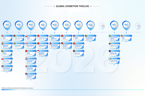 GLOBAL EXHIBITION TIMELINE
*Click to view larger image
-
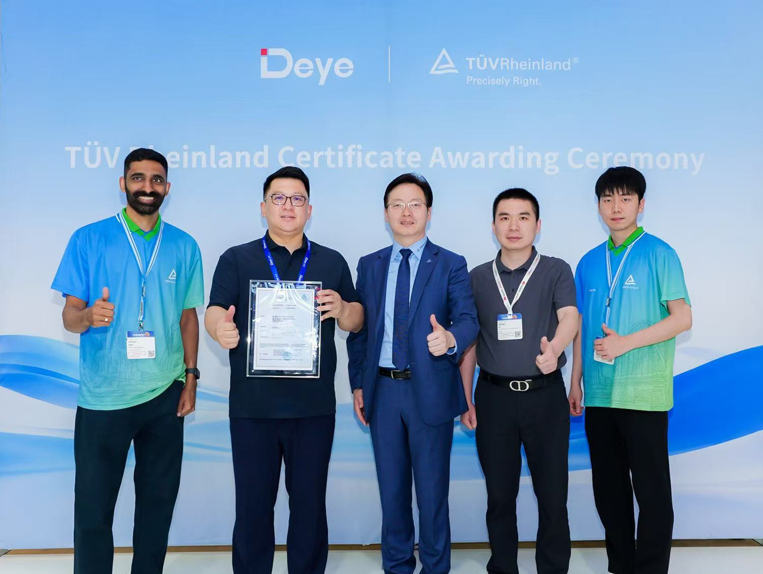 Deye Secures Multiple TÜV Rheinland Certifications at The smarter E Europe
On June 23, the opening day of The smarter E Europe 2026, Deye was officially awarded several presti...
-
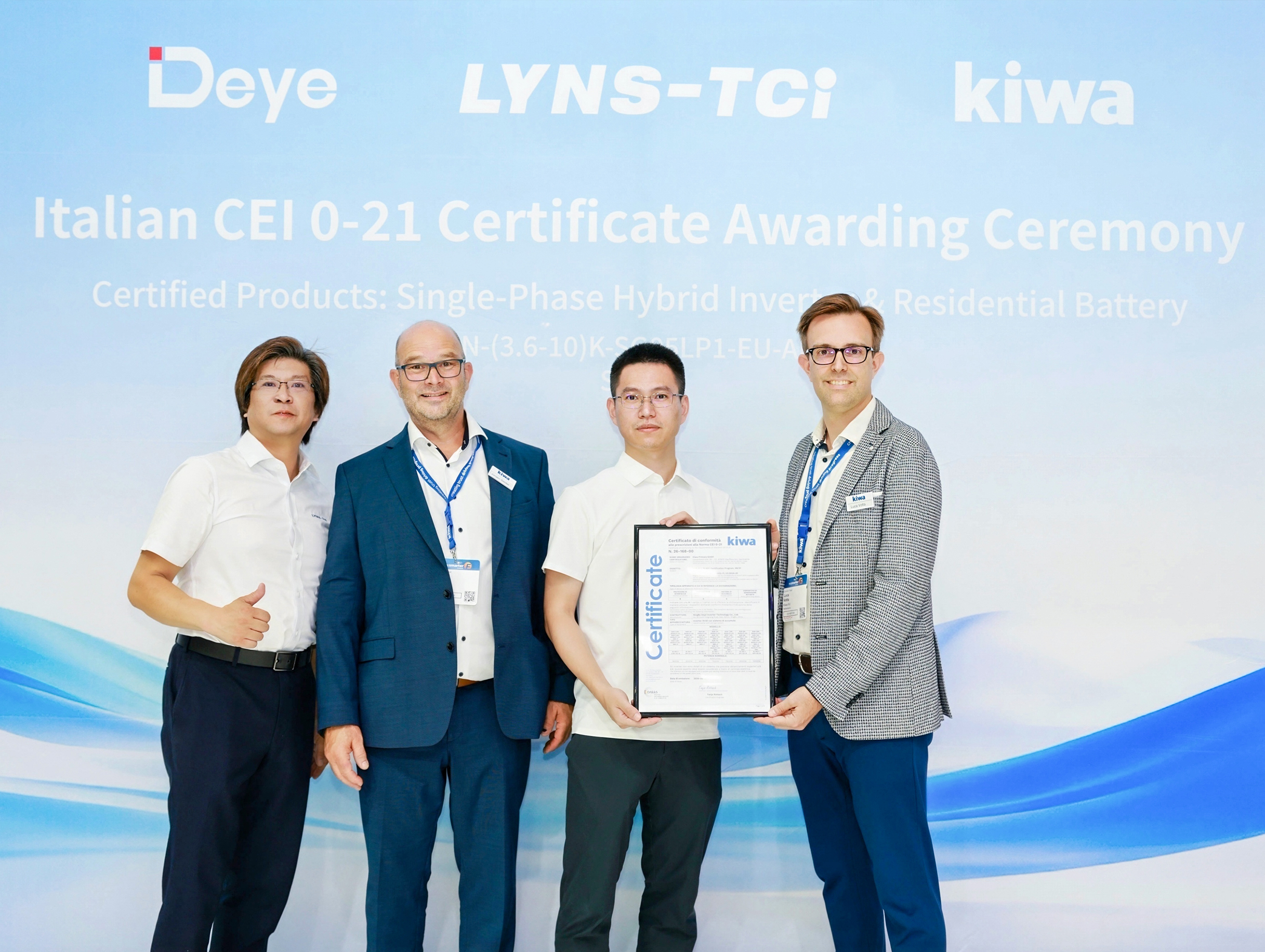 Deye Next-Gen Residential Energy Storage Products Receive Italian CEI 0-21 Certification from Kiwa
At The smarter E Europe 2026, Deye, a leading supplier of inverters and energy storage solutions, of...

Copyright@ 2024.Ningbo Deye Inverter Technology Co.,Ltd. All rights reserved. Solar Inverter Manufacturer
