 China - 简体中文
 Global - English
 Brazil - Português
 Netherlands - Dutch
 Italy - Italiano
 Germany - Deutsch
 Spain - Español
 France - Français
 Vietnam - Tiếng Việt
 Poland - Polski
 Australia - English
 Japan - 日本語
Technical Topics
How Inverters Work
The inverter is a DC to AC transformer, which is actually a process of voltage inversion with the converter. The converter converts the AC voltage of the power grid into a stable 12V DC output, while the inverter converts the 12V DC voltage output by the Adapter into a high-frequency high-voltage AC; both parts also use a more frequently used pulse width modulation (PWM) technique. Its core part is a PWM integrated controller, the Adapter uses UC3842, and the inverter uses TL5001 chip. The working voltage range of TL5001 is 3.6 ~ 40V. It has an error amplifier, a regulator, an oscillator, a PWM generator with dead zone control, a low voltage protection circuit and a short circuit protection circuit inside.
Input interface part: There are 3 signals in the input part, 12V DC input VIN, work enable voltage ENB and Panel current control signal DIM. VIN is provided by the Adapter, ENB voltage is provided by the MCU on the motherboard, its value is 0 or 3V, when ENB=0, the inverter does not work, and when ENB=3V, the inverter is in normal working state; while DIM voltage Provided by the main board, its variation range is between 0 and 5V. Different DIM values are fed back to the feedback terminal of the PWM controller, and the current provided by the inverter to the load will also be different. The smaller the DIM value, the smaller the output current of the inverter. bigger.
Voltage startup circuit: When ENB is at high level, it outputs high voltage to light up the Panel's backlight tube.
PWM controller: It consists of the following functions: internal reference voltage, error amplifier, oscillator and PWM, overvoltage protection, undervoltage protection, short circuit protection, and output transistor.
DC conversion: The voltage conversion circuit is composed of MOS switching tube and energy storage inductor. The input pulse is amplified by the push-pull amplifier and then drives the MOS tube to perform switching action, so that the DC voltage charges and discharges the inductor, so that the other end of the inductor can get AC Voltage.
LC oscillation and output circuit: ensure the 1600V voltage required for the lamp to start, and reduce the voltage to 800V after the lamp is started.
Output voltage feedback: When the load is working, the sampling voltage is fed back to stabilize the voltage output of the I inverter.
PREV:Choosing the Right Micro-Inverter for Your Solar PV Harvesting Project
NEXT:An Inverter Is a Must-Have in Your RV
Share
Product recommendations
news recommendations
-
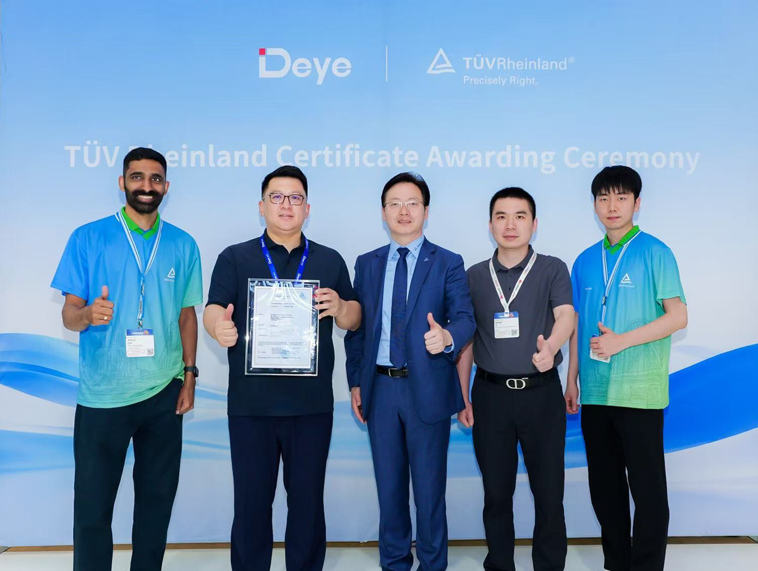 Deye Secures Multiple TÜV Rheinland Certifications at The smarter E Europe
On June 23, the opening day of The smarter E Europe 2026, Deye was officially awarded several presti...
-
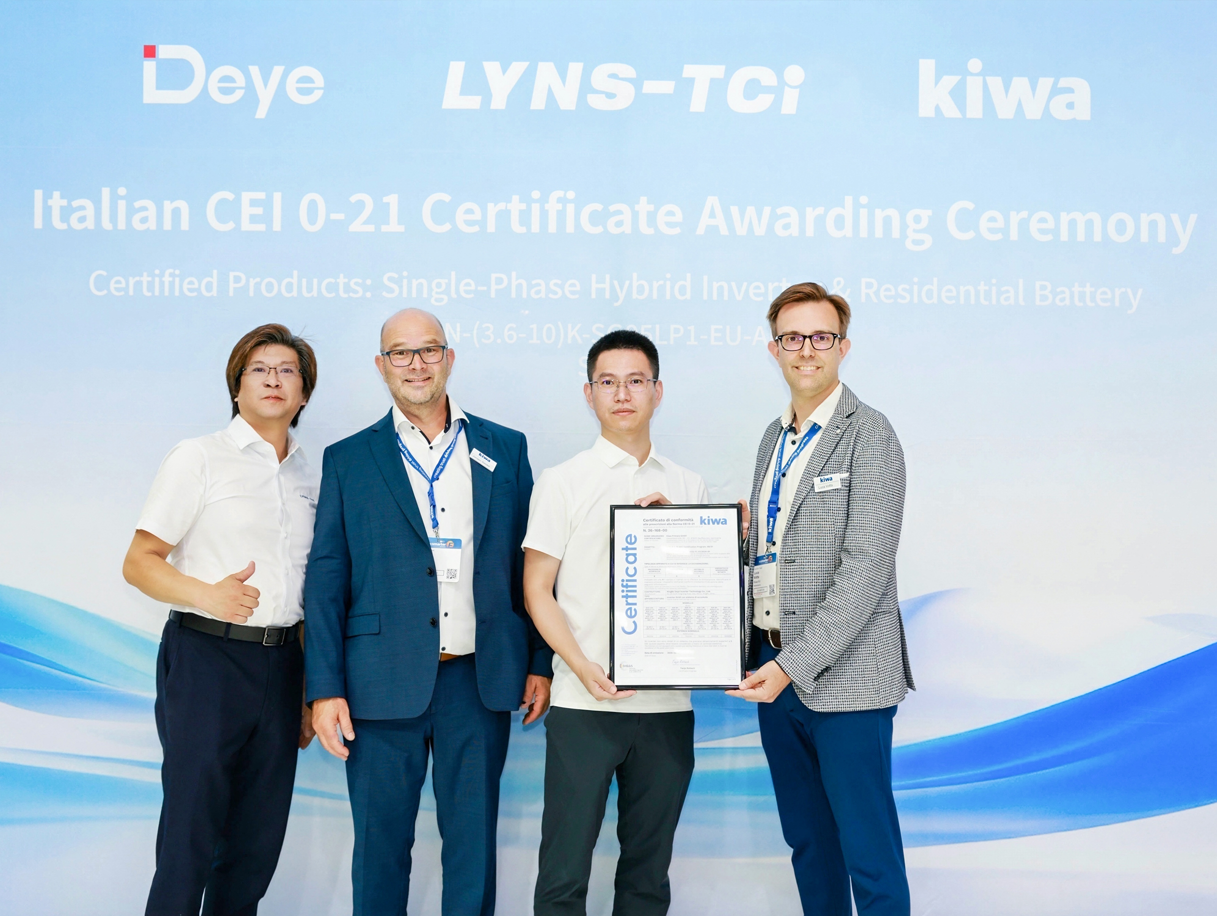 Deye Next-Gen Residential Energy Storage Products Receive Italian CEI 0-21 Certification from Kiwa
At The smarter E Europe 2026, Deye, a leading supplier of inverters and energy storage solutions, of...
-
 Deye Unveils Innovative Full-Scenario PV and Energy Storage Solutions at The smarter E Europe 2026
On June 23, The smarter E Europe, the world’s leading alliance of exhibitions for the energy industr...
Copyright@ 2024.Ningbo Deye Inverter Technology Co.,Ltd. All rights reserved. Solar Inverter Manufacturer
![]()